请注意,本文内容源自机器翻译,可能存在语法或其它翻译错误,仅供参考。如需获取准确内容,请参阅链接中的英语原文或自行翻译。
器件型号:AMC1204 嗨、大家好、我正在查看 SBAA094、我不明白 SINC 滤波器在 VHDL 代码中有关输入位流的行为:
-... 000000 ... 表示- Vref
-。。111111。。 表示 Vref
-.. 0101010 ..表示0V
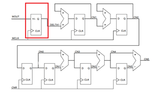
复位时 DELTA1设置为0x00 (我们使用十六进制表示法)、但当 Mout = 1时、DELTA1将递增。
无法降低 DELTA1?
M=1、则 Delta = Delta+1
不应该是 M=0、那么 Delta = Delta-1?
谢谢。