This thread has been locked.
If you have a related question, please click the "Ask a related question" button in the top right corner. The newly created question will be automatically linked to this question.
工具与软件:
尊敬的所有人:
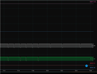
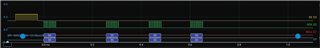
我在通过 SPI 使用 Adafruit ESP32 Heather V2与 ADS1298器件通信时遇到问题。 我已经执行了论坛中提到的所有调试步骤。 我还使用了示波器来分析信号、而 DRDY、CS 和 SCLK 信号似乎都符合预期。 我正在使用(https://github.com/ferdinandkeil/ADS129X/tree/master/examples/Serial_EMG)上的代码、也尝试了(https://github.com/adamfeuer/ADS129x-tools/tree/master/ads1298_hello_world)上的代码、 ID 寄存器无法正确回读。 此外、我尝试了一个简单的代码来配置 ADS1298和微控制器之间的通信、但设备之间似乎仍然没有通信。 我也已多次检查引脚配置、以确保已正确配置它们。 您能告诉我可能的问题是什么吗?
提前感谢。
此致!
Abdelrahman
尊敬的 Abdelrahman:
感谢您发帖。 您能否共享读取器件 ID 寄存器的 SPI 帧的逻辑分析仪捕获结果?
此致、
Ryan
e2e.ti.com/.../ADS129X_5F00_File.zip
尊敬的 Ryan:
感谢您的 快速响应。 我已经附上了一个 ZIP 文件、其中包含代码以及来自逻辑分析仪的片段、供您参考。
在代码中、我使用 HSPI 命令、因为我要处理 ESP32上的 HSPI 引脚。 如果您能查看随附的文件并就此问题提供进一步的指导、我将不胜感激。
此致!
Abdelrahman
谢谢、Abdelrahman。
这看起来与 SPI 协议设置不正确。 我没有看到 SCLK 在每个帧内切换(nCS 期间的时间为低电平)。 此外、在 MISO、MOSI 或 nDRDY 上也没有活动。
很遗憾、我们无法为 配置 ESP32本身提供支持。 我不明白此电路板为何不兼容、因此请调整您的 HSPI 配置设置 并让我知道结果。 有关 ADS1298接口的相关时序和开关特性、请参阅图1和第7.6-7.7节。
此致、
Ryan
您好、Ryan、
我调整了 SPI 配置、现在、当 nCS 处于低电平时、调整了 SCLK。 此外、我能够使用 MOSI 发送命令、但 MISO 上没有活动。 我上传了一个 zip 文件夹中的逻辑分析仪图像+代码。 如果您能为我提供进一步的指导、我将不胜感激。
#include <SPI.h> // Define the SPI pins for HSPI (on ESP32 or custom setup) #define HSPI_MISO 12 #define HSPI_MOSI 13 #define HSPI_SCLK 14 #define HSPI_SS 15 #define PWDN_PIN 32 // Define the PWDN control pin for ADS1298 static const int spiClk = 150000; // 150 kHz clock speed // Uninitialized pointer to SPI object SPIClass *hspi = NULL; void setup() { // Initialize serial for debugging Serial.begin(115200); // Initialize instance of the SPIClass attached to HSPI hspi = new SPIClass(HSPI); // Initialize SPI bus with default pins SCLK = 14, MISO = 12, MOSI = 13, SS = 15 hspi->begin(HSPI_SCLK, HSPI_MISO, HSPI_MOSI, HSPI_SS); // Set SS as output and set it high to start with (deselect) pinMode(HSPI_SS, OUTPUT); digitalWrite(HSPI_SS, HIGH); // Set up the PWDN control pin pinMode(PWDN_PIN, OUTPUT); // Power up the ADS1298 by setting PWDN pin HIGH digitalWrite(PWDN_PIN, HIGH); delay(100); // Small delay to ensure the device powers up Serial.println("ADS1298 Powered Up"); } void loop() { // Optionally: Add logic to enter Power-Down mode (if needed) // digitalWrite(PWDN_PIN, LOW); // Pull LOW to enter Power-Down mode // delay(1000); // Delay to simulate Power-Down mode byte commands[] = {0x0A, 0x20, 0x00}; // Array of commands byte response; // Variable to hold the response from the slave byte deviceID = 0x00; // Device ID // Start SPI transaction for sending the commands hspi->beginTransaction(SPISettings(spiClk, MSBFIRST, SPI_MODE1)); // Pull SS low to select the slave digitalWrite(HSPI_SS, LOW); delayMicroseconds(10); // Small delay to stabilize the signal // Send the command bytes to the slave for (int i = 0; i < sizeof(commands) / sizeof(commands[0]); i++) { response = hspi->transfer(commands[i]); // Send and receive at the same time Serial.print("Sent command: "); Serial.println(commands[i], HEX); Serial.print("Response from slave: "); Serial.println(response, HEX); // Display the response (if the slave sends any data back) } // Send and receive device ID response = hspi->transfer(deviceID); // Send and receive at the same time Serial.print("Sent device ID command: "); Serial.println(deviceID, HEX); Serial.print("Response from slave: "); Serial.println(response, HEX); // Display the response (if the slave sends any data back) // Pull SS high to deselect the slave digitalWrite(HSPI_SS, HIGH); // End SPI transaction hspi->endTransaction(); delay(1000); // Wait for a second before the next loop }
尊敬的 Abdelrahman:
在该帧中、您将发送停止命令0Ah。 但是、这仅用于停止 ADC 转换。 这就是在您为后面的 RREG 命令发送额外的 SCLK 时没有 nDRDY 或 DOUT 活动的原因。
顺便说一下-为了发送 RREG 命令0x20 0x00、您必须首先发送 SDATAC (11h)(即"停止 RDATAC")。 这与停止命令(0Ah)不同、停止命令仅用于控制 ADC 转换。 可以理解的是、这可能造成了一些混淆。
此致、
Ryan