

请注意,本文内容源自机器翻译,可能存在语法或其它翻译错误,仅供参考。如需获取准确内容,请参阅链接中的英语原文或自行翻译。
器件型号:TCAN4550EVM 主题中讨论的其他器件:TCAN4550、 MSP430FR6989、
大家好、我想将 TCAN4550连接到 CC1352R1。 是否有可用的驱动程序。
This thread has been locked.
If you have a related question, please click the "Ask a related question" button in the top right corner. The newly created question will be automatically linked to this question.
大家好、我想将 TCAN4550连接到 CC1352R1。 是否有可用的驱动程序。
您好、Joju、
我不知道该 MCU 可与 TCAN4550配合使用的任何专用软件。 可以修改为 MSP430FR6989编写的演示代码中的驱动程序(可在 TCAN4550的存储页面上找到)以与此 MCU 配合使用。 将 SPI 和外部引脚配置更改为使用相应的 CC1352R1值后、其余函数是通用 C 方法、可按演示所示使用。
请告诉我这是否可行、以及您对演示软件是否有任何疑问。
此致、
Eric Schott
主席先生,
感谢您的回答。
今天、我们能够使 TCAN4550进入正常模式。 (处于待机状态的原因是:CAN 模块的电源电压低于5V)
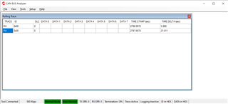
现在、我们无法在 CAN 总线分析仪中看到数据、速度限制为1Mbps。
在演示中,将代码 数据速度设置为2Mbps。
您能指导我们将 NBTP、DBTP 和 TDCR 设置为1Mbps。 TCAN4550EVM 模块具有40MHz 晶体。
谢谢
Joju John
您好、Joju、
可以通过在 main.c 的 Init_CAN()函数中将 cccrConfig.FDOE 和 cccrConfig.BRSE 变量设置为0来禁用 CAN FD 这会将器件设置为仅对 CAN 帧的所有部分使用标称位速率(默认配置为40MHz 晶体为500kbps)。 您还可以选择注释掉 TCANDataTiming 部分、因为禁用 CANFD 时不会使用该部分。
此致、
Eric Schott
尊敬的先生:
感谢您的支持。
我们尝试以500Kbps 的速率在普通 CAN 总线中进行连接。 初始化代码如下所示:
/*
 * Configure the TCAN4550
 */
void Init_CAN(void)
{
    uint32_t readValue;
    CAN_SPI_Init();

    TCAN4x5x_Device_ClearSPIERR();                              // Clear any SPI ERR flags that might be set as a result of our pin mux changing during MCU startup

    /* Step one attempt to clear all interrupts */
    TCAN4x5x_Device_Interrupt_Enable dev_ie = {0};              // Initialize to 0 to all bits are set to 0.
    TCAN4x5x_Device_ConfigureInterruptEnable(&dev_ie);          // Disable all non-MCAN related interrupts for simplicity

    TCAN4x5x_Device_Interrupts dev_ir = {0};                    // Setup a new MCAN IR object for easy interrupt checking
    TCAN4x5x_Device_ReadInterrupts(&dev_ir);                    // Request that the struct be updated with current DEVICE (not MCAN) interrupt values

    if (dev_ir.PWRON)                                           // If the Power On interrupt flag is set
        TCAN4x5x_Device_ClearInterrupts(&dev_ir);               // Clear it because if it's not cleared within ~4 minutes, it goes to sleep

    /* Configure the CAN bus speeds NBTP & DBTP*/
    TCAN4x5x_MCAN_Nominal_Timing_Simple TCANNomTiming = {0};    // 500k arbitration with a 40 MHz crystal ((40E6 / 2) / (32 + 8) = 500E3)
    TCANNomTiming.NominalBitRatePrescaler = 2;                  //2, 1Mk arbitration with a 40 MHz crystal ((40E6 / 1) / (32 + 8) = 1E6)
    TCANNomTiming.NominalTqBeforeSamplePoint = 32;              //32
    TCANNomTiming.NominalTqAfterSamplePoint = 8;                //8

    TCAN4x5x_MCAN_Data_Timing_Simple TCANDataTiming = {0};      // 2 Mbps CAN FD with a 40 MHz crystal (40E6 / (15 + 5) = 2E6)
    TCANDataTiming.DataBitRatePrescaler = 2;                    // previous data 1, Now 1 Mbps CAN FD with a 40 MHz crystal ((40E6 / 2) / (15 + 5) = 1E6)
    TCANDataTiming.DataTqBeforeSamplePoint = 15;
    TCANDataTiming.DataTqAfterSamplePoint = 5;

    /* Configure the MCAN core settings */
    TCAN4x5x_MCAN_CCCR_Config cccrConfig = {0};                 // Remember to initialize to 0, or you'll get random garbage!
    cccrConfig.FDOE = 0;                                        //1, CAN FD mode enable
    cccrConfig.BRSE = 0;                                        //1, CAN FD Bit rate switch enable

    /* Configure the default CAN packet filtering settings */
    TCAN4x5x_MCAN_Global_Filter_Configuration gfc = {0};
    gfc.RRFE = 1;                                               // Reject remote frames (TCAN4x5x doesn't support this)
    gfc.RRFS = 1;                                               // Reject remote frames (TCAN4x5x doesn't support this)
    gfc.ANFE = TCAN4x5x_GFC_ACCEPT_INTO_RXFIFO0;                // Default behavior if incoming message doesn't match a filter is to accept into RXFIO0 for extended ID messages (29 bit IDs)
    gfc.ANFS = TCAN4x5x_GFC_ACCEPT_INTO_RXFIFO0;                // Default behavior if incoming message doesn't match a filter is to accept into RXFIO0 for standard ID messages (11 bit IDs)

    /* ************************************************************************
     * In the next configuration block, we will set the MCAN core up to have:
     *   - 1 SID filter element
     *   - 1 XID Filter element
     *   - 5 RX FIFO 0 elements
     *   - RX FIFO 0 supports data payloads up to 64 bytes
     *   - RX FIFO 1 and RX Buffer will not have any elements, but we still set their data payload sizes, even though it's not required
     *   - No TX Event FIFOs
     *   - 2 Transmit buffers supporting up to 64 bytes of data payload
     */
    TCAN4x5x_MRAM_Config MRAMConfiguration = {0};
    MRAMConfiguration.SIDNumElements = 1;                       // Standard ID number of elements, you MUST have a filter written to MRAM for each element defined
    MRAMConfiguration.XIDNumElements = 1;                       // Extended ID number of elements, you MUST have a filter written to MRAM for each element defined
    MRAMConfiguration.Rx0NumElements = 5;                       // RX0 Number of elements
    MRAMConfiguration.Rx0ElementSize = MRAM_64_Byte_Data;       // RX0 data payload size
    MRAMConfiguration.Rx1NumElements = 0;                       // RX1 number of elements
    MRAMConfiguration.Rx1ElementSize = MRAM_64_Byte_Data;       // RX1 data payload size
    MRAMConfiguration.RxBufNumElements = 0;                     // RX buffer number of elements
    MRAMConfiguration.RxBufElementSize = MRAM_64_Byte_Data;     // RX buffer data payload size
    MRAMConfiguration.TxEventFIFONumElements = 0;               // TX Event FIFO number of elements
    MRAMConfiguration.TxBufferNumElements = 2;                  // TX buffer number of elements
    MRAMConfiguration.TxBufferElementSize = MRAM_64_Byte_Data;  // TX buffer data payload size


    /* Configure the MCAN core with the settings above, the changes in this block are write protected registers,      *
     * so it makes the most sense to do them all at once, so we only unlock and lock once                             */

    TCAN4x5x_MCAN_EnableProtectedRegisters();                   // Start by making protected registers accessible
    TCAN4x5x_MCAN_ConfigureCCCRRegister(&cccrConfig);           // Enable FD mode and Bit rate switching
    TCAN4x5x_MCAN_ConfigureGlobalFilter(&gfc);                  // Configure the global filter configuration (Default CAN message behavior)
    TCAN4x5x_MCAN_ConfigureNominalTiming_Simple(&TCANNomTiming);// Setup nominal/arbitration bit timing
//    TCAN4x5x_MCAN_ConfigureDataTiming_Simple(&TCANDataTiming);  // Setup CAN FD timing
    TCAN4x5x_MRAM_Clear();                                      // Clear all of MRAM (Writes 0's to all of it)
    TCAN4x5x_MRAM_Configure(&MRAMConfiguration);                // Set up the applicable registers related to MRAM configuration
    TCAN4x5x_MCAN_DisableProtectedRegisters();                  // Disable protected write and take device out of INIT mode


    /* Set the interrupts we want to enable for MCAN */
    TCAN4x5x_MCAN_Interrupt_Enable mcan_ie = {0};               // Remember to initialize to 0, or you'll get random garbage!
    mcan_ie.RF0NE = 1;                                          // RX FIFO 0 new message interrupt enable

    TCAN4x5x_MCAN_ConfigureInterruptEnable(&mcan_ie);           // Enable the appropriate registers


    /* Setup filters, this filter will mark any message with ID 0x055 as a priority message */
    TCAN4x5x_MCAN_SID_Filter SID_ID = {0};
    SID_ID.SFT = TCAN4x5x_SID_SFT_CLASSIC;                      // SFT: Standard filter type. Configured as a classic filter
    SID_ID.SFEC = TCAN4x5x_SID_SFEC_PRIORITYSTORERX0;           // Standard filter element configuration, store it in RX fifo 0 as a priority message
    SID_ID.SFID1 = 0x055;                                       // SFID1 (Classic mode Filter)
    SID_ID.SFID2 = 0x7FF;                                       // SFID2 (Classic mode Mask)
    TCAN4x5x_MCAN_WriteSIDFilter(0, &SID_ID);                   // Write to the MRAM


    /* Store ID 0x12345678 as a priority message */
    TCAN4x5x_MCAN_XID_Filter XID_ID = {0};
    XID_ID.EFT = TCAN4x5x_XID_EFT_CLASSIC;                      // EFT
    XID_ID.EFEC = TCAN4x5x_XID_EFEC_PRIORITYSTORERX0;           // EFEC
    XID_ID.EFID1 = 0x12345678;                                  // EFID1 (Classic mode filter)
    XID_ID.EFID2 = 0x1FFFFFFF;                                  // EFID2 (Classic mode mask)
    TCAN4x5x_MCAN_WriteXIDFilter(0, &XID_ID);                   // Write to the MRAM

    /* Configure the TCAN4550 Non-CAN-related functions */
    TCAN4x5x_DEV_CONFIG devConfig = {0};                        // Remember to initialize to 0, or you'll get random garbage!
    devConfig.SWE_DIS = 0;                                      // 0, Keep Sleep Wake Error Enabled (it's a disable bit, not an enable)
    devConfig.DEVICE_RESET = 0;                                 // Not requesting a software reset
    devConfig.WD_EN = 0;                                        // Watchdog disabled
    devConfig.nWKRQ_CONFIG = 0;                                 // Mirror INH function (default)
    devConfig.INH_DIS = 0;                                      // INH enabled (default)
    devConfig.GPIO1_GPO_CONFIG = TCAN4x5x_DEV_CONFIG_GPO1_MCAN_INT1;    // MCAN nINT 1 (default)
    devConfig.FAIL_SAFE_EN = 0;                                 // 0, Failsafe disabled (default)
    devConfig.GPIO1_CONFIG = TCAN4x5x_DEV_CONFIG_GPIO1_CONFIG_GPO;      // GPIO set as GPO (Default)
    devConfig.WD_ACTION = TCAN4x5x_DEV_CONFIG_WDT_ACTION_nINT;  // Watchdog set an interrupt (default)
    devConfig.WD_BIT_RESET = 0;                                 // Don't reset the watchdog
    devConfig.nWKRQ_VOLTAGE = 0;                                // Set nWKRQ to internal voltage rail (default)
    devConfig.GPO2_CONFIG = TCAN4x5x_DEV_CONFIG_GPO2_NO_ACTION; // GPO2 has no behavior (default)
    devConfig.CLK_REF = 1;                                      // Input crystal is a 40 MHz crystal (default)
    devConfig.WAKE_CONFIG = TCAN4x5x_DEV_CONFIG_WAKE_BOTH_EDGES;// Wake pin can be triggered by either edge (default)
    TCAN4x5x_Device_Configure(&devConfig);                      // Configure the device with the above configuration

//    while(!TCAN4x5x_Device_SetMode(TCAN4x5x_DEVICE_MODE_NORMAL));
    TCAN4x5x_Device_SetMode(TCAN4x5x_DEVICE_MODE_NORMAL);       // Set to normal mode, since configuration is done. This line turns on the transceiver

    TCAN4x5x_MCAN_ClearInterruptsAll();                         // Resets all MCAN interrupts (does NOT include any SPIERR interrupts)


    /* Define the CAN message we want to send*/
    TCAN4x5x_MCAN_TX_Header header = {0};           // Remember to initialize to 0, or you'll get random garbage!
    uint8_t data[4] = {0x55, 0x66, 0x77, 0x88};     // Define the data payload
    header.DLC = MCAN_DLC_4B;                       // Set the DLC to be equal to or less than the data payload (it is ok to pass a 64 byte data array into the WriteTXFIFO function if your DLC is 8 bytes, only the first 8 bytes will be read)
    header.ID = 0x144;                              // Set the ID
    header.FDF = 0;                                 // CAN FD frame enabled
    header.BRS = 0;                                 // Bit rate switch enabled
    header.EFC = 0;
    header.MM  = 0;
    header.RTR = 0;
    header.XTD = 0;                                 // We are not using an extended ID in this example
    header.ESI = 0;                                 // Error state indicator


    TCAN4x5x_MCAN_WriteTXBuffer(0, &header, data);  // This function actually writes the header and data payload to the TCAN's MRAM in the specified TX queue number. It returns the bit necessary to write to TXBAR,
                                                    // but does not necessarily require you to use it. In this example, we won't, so that we can send the data queued up at a later point.

    /* Let's make a different CAN message */
    data[0] = 0x11;
    data[1] = 0x22;
    data[2] = 0x33;
    data[3] = 0x44;                                 // Define the data payload

    header.DLC = MCAN_DLC_4B;                       // Set the DLC to be equal to or less than the data payload (it is ok to pass a 64 byte data array into the WriteTXFIFO function if your DLC is 8 bytes, only the first 8 bytes will be read)
    header.ID = 0x123;                              // Set the ID
    header.FDF = 0;                                 // CAN FD frame enabled
    header.BRS = 0;                                 // Bit rate switch enabled
    header.EFC = 0;
    header.MM  = 0;
    header.RTR = 0;
    header.XTD = 0;                                 // We are not using an extended ID in this example
    header.ESI = 0;                                 // Error state indicator

    TCAN4x5x_MCAN_WriteTXBuffer(1, &header, data);  // This line writes the data and header to TX FIFO 1
    TCAN4x5x_MCAN_TransmitBufferContents(1);        // Request that TX Buffer 1 be transmitted

    TCAN4x5x_MCAN_TransmitBufferContents(0);        // Now we can send the TX FIFO element 0 data that we had queued up earlier but didn't send.

}
CAN 分析仪的工作方式仍然相同。
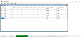
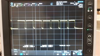
来自 CAN 分析仪的信号也如上所示。
谢谢
Joju John
您好、Joju、
对代码的更改在这里看起来很好。 除了我们讨论的更改之外、我还没有进行过其他回顾、因此如果您对某些特定问题有任何顾虑、请指出、我可以查看一下。
TCAN4550似乎正在发送一系列错误帧。 当器件无法识别总线上其他节点的任何确认时、可能会发生这种情况。 在我使用另一个有源节点将节点连接到总线之前、我在自己的测试中通常会看到这一点。 请确保 CAN 分析器或其他节点配置为确认 TCAN4550发送的信息。
此致、
Eric Schott
/*
 * main.c
 * Author: Texas Instruments
 * Date: 4/25/2019
 *
 * Description: A basic version of code to set up and receive a packet.
 *  - This is designed to work with the EVM the BOOSTXL-CANFD-LIN Rev 1.0 Boosterpack
 *  - It assumes TCAN4550 Oscillator of 40 MHz
 *  - Sets CAN arbitration rate at 500 kBaud
 *  - Sets CAN FD data phase for 2 MBaud
 *  - The interrupt pin is used for signal a received message, rather than polling
 *
 *   Pressing S1 will transmit a CAN message. S1 is on the MSP430FR6989 launchpad to the left.
 *
 *  Pinout
 *   - P1.4 SPI Clock / SCLK
 *   - P1.6 MOSI / SDI
 *   - P1.7 MISO / SDO
 *   - P2.5 SPI Chip Select / nCS
 *
 *   - P2.3 MCAN Interrupt 1 / nINT
 *   - Ground wire is important
 *
 *
 *
 * Copyright (c) 2019 Texas Instruments Incorporated.  All rights reserved.
 * Software License Agreement
 *
 * Redistribution and use in source and binary forms, with or without
 * modification, are permitted provided that the following conditions
 * are met:
 *
 * Redistributions of source code must retain the above copyright
 * notice, this list of conditions and the following disclaimer.
 *
 * Redistributions in binary form must reproduce the above copyright
 * notice, this list of conditions and the following disclaimer in the
 * documentation and/or other materials provided with the
 * distribution.
 *
 * Neither the name of Texas Instruments Incorporated nor the names of
 * its contributors may be used to endorse or promote products derived
 * from this software without specific prior written permission.
 *
 * THIS SOFTWARE IS PROVIDED BY THE COPYRIGHT HOLDERS AND CONTRIBUTORS
 * "AS IS" AND ANY EXPRESS OR IMPLIED WARRANTIES, INCLUDING, BUT NOT
 * LIMITED TO, THE IMPLIED WARRANTIES OF MERCHANTABILITY AND FITNESS FOR
 * A PARTICULAR PURPOSE ARE DISCLAIMED. IN NO EVENT SHALL THE COPYRIGHT
 * OWNER OR CONTRIBUTORS BE LIABLE FOR ANY DIRECT, INDIRECT, INCIDENTAL,
 * SPECIAL, EXEMPLARY, OR CONSEQUENTIAL DAMAGES (INCLUDING, BUT NOT
 * LIMITED TO, PROCUREMENT OF SUBSTITUTE GOODS OR SERVICES; LOSS OF USE,
 * DATA, OR PROFITS; OR BUSINESS INTERRUPTION) HOWEVER CAUSED AND ON ANY
 * THEORY OF LIABILITY, WHETHER IN CONTRACT, STRICT LIABILITY, OR TORT
 * (INCLUDING NEGLIGENCE OR OTHERWISE) ARISING IN ANY WAY OUT OF THE USE
 * OF THIS SOFTWARE, EVEN IF ADVISED OF THE POSSIBILITY OF SUCH DAMAGE.
 */

#include <driverlib.h>
#include <msp430.h>

#include "tcan4x5x/TCAN4550.h"


void Init_GPIO(void);
void Init_Clock(void);
void Init_SPI(void);
void Init_CAN(void);

volatile uint8_t TCAN_Int_Cnt = 0;                  // A variable used to keep track of interrupts the MCAN Interrupt pin


int
main(void)
{
    /***********************************
     * MSP430 Specific Initializations *
     ***********************************/
    WDT_A_hold(__MSP430_BASEADDRESS_WDT_A__);
    Init_GPIO();                                    // Set up GPIOs for SPI and TCAN4550 connections
    Init_Clock();                                   // Set up the system clocks for 16 MHz (on the MSP430)
    Init_SPI();                                     // Initialize the SPI hardware module for 2 MHz SPI
    GPIO_clearInterrupt(GPIO_PORT_P1, GPIO_PIN1);   // Clear any interrupts on pin 1.1 before we enable global interrupts
    GPIO_clearInterrupt(GPIO_PORT_P2, GPIO_PIN3);   // Clear any interrupts on pin 2.3 before we enable global interrupts
    __enable_interrupt();


    /*********************************************
     * Everything at this point is for TCAN4550  *
     *********************************************/
    Init_CAN();                                     // Run the main MCAN configuration sequence. The bulk of the configuration is in this!

    /* Define the CAN message we want to send*/
    TCAN4x5x_MCAN_TX_Header header = {0};           // Remember to initialize to 0, or you'll get random garbage!
    uint8_t data[4] = {0x55, 0x66, 0x77, 0x88};     // Define the data payload
    header.DLC = MCAN_DLC_4B;                       // Set the DLC to be equal to or less than the data payload (it is ok to pass a 64 byte data array into the WriteTXFIFO function if your DLC is 8 bytes, only the first 8 bytes will be read)
    header.ID = 0x144;                              // Set the ID
    header.FDF = 0;                                 // CAN FD frame enabled
    header.BRS = 0;                                 // Bit rate switch enabled
    header.EFC = 0;
    header.MM  = 0;
    header.RTR = 0;
    header.XTD = 0;                                 // We are not using an extended ID in this example
    header.ESI = 0;                                 // Error state indicator


    TCAN4x5x_MCAN_WriteTXBuffer(0, &header, data);  // This function actually writes the header and data payload to the TCAN's MRAM in the specified TX queue number. It returns the bit necessary to write to TXBAR,
                                                    // but does not necessarily require you to use it. In this example, we won't, so that we can send the data queued up at a later point.

    /* Let's make a different CAN message */
    data[0] = 0x11;
    data[1] = 0x22;
    data[2] = 0x33;
    data[3] = 0x44;                                 // Define the data payload

    header.DLC = MCAN_DLC_4B;                       // Set the DLC to be equal to or less than the data payload (it is ok to pass a 64 byte data array into the WriteTXFIFO function if your DLC is 8 bytes, only the first 8 bytes will be read)
    header.ID = 0x123;                              // Set the ID
    header.FDF = 0;                                 // CAN FD frame enabled
    header.BRS = 0;                                 // Bit rate switch enabled
    header.EFC = 0;
    header.MM  = 0;
    header.RTR = 0;
    header.XTD = 0;                                 // We are not using an extended ID in this example
    header.ESI = 0;                                 // Error state indicator

    TCAN4x5x_MCAN_WriteTXBuffer(1, &header, data);  // This line writes the data and header to TX FIFO 1
    TCAN4x5x_MCAN_TransmitBufferContents(1);        // Request that TX Buffer 1 be transmitted


    TCAN4x5x_MCAN_TransmitBufferContents(0);        // Now we can send the TX FIFO element 0 data that we had queued up earlier but didn't send.

    while (1)
    {
        if (TCAN_Int_Cnt > 0 )
        {
            TCAN_Int_Cnt--;
            TCAN4x5x_Device_Interrupts dev_ir = {0};            // Define a new Device IR object for device (non-CAN) interrupt checking
            TCAN4x5x_MCAN_Interrupts mcan_ir = {0};             // Setup a new MCAN IR object for easy interrupt checking
            TCAN4x5x_Device_ReadInterrupts(&dev_ir);            // Read the device interrupt register
            TCAN4x5x_MCAN_ReadInterrupts(&mcan_ir);             // Read the interrupt register

            if (dev_ir.SPIERR)                                  // If the SPIERR flag is set
                TCAN4x5x_Device_ClearSPIERR();                  // Clear the SPIERR flag

            if (mcan_ir.RF0N)                                   // If a new message in RX FIFO 0
            {
                TCAN4x5x_MCAN_RX_Header MsgHeader = {0};        // Initialize to 0 or you'll get garbage
                uint8_t numBytes = 0;                           // Used since the ReadNextFIFO function will return how many bytes of data were read
                uint8_t dataPayload[64] = {0};                  // Used to store the received data

                TCAN4x5x_MCAN_ClearInterrupts(&mcan_ir);        // Clear any of the interrupt bits that are set.

                numBytes = TCAN4x5x_MCAN_ReadNextFIFO( RXFIFO0, &MsgHeader, dataPayload);   // This will read the next element in the RX FIFO 0

                // numBytes will have the number of bytes it transfered in it. Or you can decode the DLC value in MsgHeader.DLC
                // The data is now in dataPayload[], and message specific information is in the MsgHeader struct.
                if (MsgHeader.ID == 0x0AA)      // Example of how you can do an action based off a received address
                {
                    // Do something
                }
            }
        }
    }
}

/*
 * Configure the TCAN4550
 */
void
Init_CAN(void)
{
    TCAN4x5x_Device_ClearSPIERR();                              // Clear any SPI ERR flags that might be set as a result of our pin mux changing during MCU startup

    /* Step one attempt to clear all interrupts */
    TCAN4x5x_Device_Interrupt_Enable dev_ie = {0};              // Initialize to 0 to all bits are set to 0.
    TCAN4x5x_Device_ConfigureInterruptEnable(&dev_ie);          // Disable all non-MCAN related interrupts for simplicity

    TCAN4x5x_Device_Interrupts dev_ir = {0};                    // Setup a new MCAN IR object for easy interrupt checking
    TCAN4x5x_Device_ReadInterrupts(&dev_ir);                    // Request that the struct be updated with current DEVICE (not MCAN) interrupt values

    if (dev_ir.PWRON)                                           // If the Power On interrupt flag is set
        TCAN4x5x_Device_ClearInterrupts(&dev_ir);               // Clear it because if it's not cleared within ~4 minutes, it goes to sleep

    /* Configure the CAN bus speeds */
    TCAN4x5x_MCAN_Nominal_Timing_Simple TCANNomTiming = {0};    // 500k arbitration with a 40 MHz crystal ((40E6 / 2) / (32 + 8) = 500E3)
    TCANNomTiming.NominalBitRatePrescaler = 2;
    TCANNomTiming.NominalTqBeforeSamplePoint = 32;
    TCANNomTiming.NominalTqAfterSamplePoint = 8;

    TCAN4x5x_MCAN_Data_Timing_Simple TCANDataTiming = {0};      // 2 Mbps CAN FD with a 40 MHz crystal (40E6 / (15 + 5) = 2E6)
    TCANDataTiming.DataBitRatePrescaler = 1;
    TCANDataTiming.DataTqBeforeSamplePoint = 15;
    TCANDataTiming.DataTqAfterSamplePoint = 5;

    /* Configure the MCAN core settings */
    TCAN4x5x_MCAN_CCCR_Config cccrConfig = {0};                 // Remember to initialize to 0, or you'll get random garbage!
    cccrConfig.FDOE = 0;                                        // CAN FD mode enable
    cccrConfig.BRSE = 0;                                        // CAN FD Bit rate switch enable

    /* Configure the default CAN packet filtering settings */
    TCAN4x5x_MCAN_Global_Filter_Configuration gfc = {0};
    gfc.RRFE = 1;                                               // Reject remote frames (TCAN4x5x doesn't support this)
    gfc.RRFS = 1;                                               // Reject remote frames (TCAN4x5x doesn't support this)
    gfc.ANFE = TCAN4x5x_GFC_ACCEPT_INTO_RXFIFO0;                // Default behavior if incoming message doesn't match a filter is to accept into RXFIO0 for extended ID messages (29 bit IDs)
    gfc.ANFS = TCAN4x5x_GFC_ACCEPT_INTO_RXFIFO0;                // Default behavior if incoming message doesn't match a filter is to accept into RXFIO0 for standard ID messages (11 bit IDs)

    /* ************************************************************************
     * In the next configuration block, we will set the MCAN core up to have:
     *   - 1 SID filter element
     *   - 1 XID Filter element
     *   - 5 RX FIFO 0 elements
     *   - RX FIFO 0 supports data payloads up to 64 bytes
     *   - RX FIFO 1 and RX Buffer will not have any elements, but we still set their data payload sizes, even though it's not required
     *   - No TX Event FIFOs
     *   - 2 Transmit buffers supporting up to 64 bytes of data payload
     */
    TCAN4x5x_MRAM_Config MRAMConfiguration = {0};
    MRAMConfiguration.SIDNumElements = 1;                       // Standard ID number of elements, you MUST have a filter written to MRAM for each element defined
    MRAMConfiguration.XIDNumElements = 1;                       // Extended ID number of elements, you MUST have a filter written to MRAM for each element defined
    MRAMConfiguration.Rx0NumElements = 5;                       // RX0 Number of elements
    MRAMConfiguration.Rx0ElementSize = MRAM_64_Byte_Data;       // RX0 data payload size
    MRAMConfiguration.Rx1NumElements = 0;                       // RX1 number of elements
    MRAMConfiguration.Rx1ElementSize = MRAM_64_Byte_Data;       // RX1 data payload size
    MRAMConfiguration.RxBufNumElements = 0;                     // RX buffer number of elements
    MRAMConfiguration.RxBufElementSize = MRAM_64_Byte_Data;     // RX buffer data payload size
    MRAMConfiguration.TxEventFIFONumElements = 0;               // TX Event FIFO number of elements
    MRAMConfiguration.TxBufferNumElements = 2;                  // TX buffer number of elements
    MRAMConfiguration.TxBufferElementSize = MRAM_64_Byte_Data;  // TX buffer data payload size


    /* Configure the MCAN core with the settings above, the changes in this block are write protected registers,      *
     * so it makes the most sense to do them all at once, so we only unlock and lock once                             */

    TCAN4x5x_MCAN_EnableProtectedRegisters();                   // Start by making protected registers accessible
    TCAN4x5x_MCAN_ConfigureCCCRRegister(&cccrConfig);           // Enable FD mode and Bit rate switching
    TCAN4x5x_MCAN_ConfigureGlobalFilter(&gfc);                  // Configure the global filter configuration (Default CAN message behavior)
    TCAN4x5x_MCAN_ConfigureNominalTiming_Simple(&TCANNomTiming);// Setup nominal/arbitration bit timing
//    TCAN4x5x_MCAN_ConfigureDataTiming_Simple(&TCANDataTiming);  // Setup CAN FD timing
    TCAN4x5x_MRAM_Clear();                                      // Clear all of MRAM (Writes 0's to all of it)
    TCAN4x5x_MRAM_Configure(&MRAMConfiguration);                // Set up the applicable registers related to MRAM configuration
    TCAN4x5x_MCAN_DisableProtectedRegisters();                  // Disable protected write and take device out of INIT mode


    /* Set the interrupts we want to enable for MCAN */
    TCAN4x5x_MCAN_Interrupt_Enable mcan_ie = {0};               // Remember to initialize to 0, or you'll get random garbage!
    mcan_ie.RF0NE = 1;                                          // RX FIFO 0 new message interrupt enable

    TCAN4x5x_MCAN_ConfigureInterruptEnable(&mcan_ie);           // Enable the appropriate registers


    /* Setup filters, this filter will mark any message with ID 0x055 as a priority message */
    TCAN4x5x_MCAN_SID_Filter SID_ID = {0};
    SID_ID.SFT = TCAN4x5x_SID_SFT_CLASSIC;                      // SFT: Standard filter type. Configured as a classic filter
    SID_ID.SFEC = TCAN4x5x_SID_SFEC_PRIORITYSTORERX0;           // Standard filter element configuration, store it in RX fifo 0 as a priority message
    SID_ID.SFID1 = 0x055;                                       // SFID1 (Classic mode Filter)
    SID_ID.SFID2 = 0x7FF;                                       // SFID2 (Classic mode Mask)
    TCAN4x5x_MCAN_WriteSIDFilter(0, &SID_ID);                   // Write to the MRAM


    /* Store ID 0x12345678 as a priority message */
    TCAN4x5x_MCAN_XID_Filter XID_ID = {0};
    XID_ID.EFT = TCAN4x5x_XID_EFT_CLASSIC;                      // EFT
    XID_ID.EFEC = TCAN4x5x_XID_EFEC_PRIORITYSTORERX0;           // EFEC
    XID_ID.EFID1 = 0x12345678;                                  // EFID1 (Classic mode filter)
    XID_ID.EFID2 = 0x1FFFFFFF;                                  // EFID2 (Classic mode mask)
    TCAN4x5x_MCAN_WriteXIDFilter(0, &XID_ID);                   // Write to the MRAM

    /* Configure the TCAN4550 Non-CAN-related functions */
    TCAN4x5x_DEV_CONFIG devConfig = {0};                        // Remember to initialize to 0, or you'll get random garbage!
    devConfig.SWE_DIS = 0;                                      // Keep Sleep Wake Error Enabled (it's a disable bit, not an enable)
    devConfig.DEVICE_RESET = 0;                                 // Not requesting a software reset
    devConfig.WD_EN = 0;                                        // Watchdog disabled
    devConfig.nWKRQ_CONFIG = 0;                                 // Mirror INH function (default)
    devConfig.INH_DIS = 0;                                      // INH enabled (default)
    devConfig.GPIO1_GPO_CONFIG = TCAN4x5x_DEV_CONFIG_GPO1_MCAN_INT1;    // MCAN nINT 1 (default)
    devConfig.FAIL_SAFE_EN = 0;                                 // Failsafe disabled (default)
    devConfig.GPIO1_CONFIG = TCAN4x5x_DEV_CONFIG_GPIO1_CONFIG_GPO;      // GPIO set as GPO (Default)
    devConfig.WD_ACTION = TCAN4x5x_DEV_CONFIG_WDT_ACTION_nINT;  // Watchdog set an interrupt (default)
    devConfig.WD_BIT_RESET = 0;                                 // Don't reset the watchdog
    devConfig.nWKRQ_VOLTAGE = 0;                                // Set nWKRQ to internal voltage rail (default)
    devConfig.GPO2_CONFIG = TCAN4x5x_DEV_CONFIG_GPO2_NO_ACTION; // GPO2 has no behavior (default)
    devConfig.CLK_REF = 1;                                      // Input crystal is a 40 MHz crystal (default)
    devConfig.WAKE_CONFIG = TCAN4x5x_DEV_CONFIG_WAKE_BOTH_EDGES;// Wake pin can be triggered by either edge (default)
    TCAN4x5x_Device_Configure(&devConfig);                      // Configure the device with the above configuration

    TCAN4x5x_Device_SetMode(TCAN4x5x_DEVICE_MODE_NORMAL);       // Set to normal mode, since configuration is done. This line turns on the transceiver

    TCAN4x5x_MCAN_ClearInterruptsAll();                         // Resets all MCAN interrupts (does NOT include any SPIERR interrupts)
}


/*
 * GPIO Initialization
 */
void
Init_GPIO()
{
    // Set all GPIO pins to output low to prevent floating input and reduce power consumption
    GPIO_setOutputLowOnPin(GPIO_PORT_P1, GPIO_PIN0|GPIO_PIN1|GPIO_PIN2|GPIO_PIN3|GPIO_PIN4|GPIO_PIN5|GPIO_PIN6|GPIO_PIN7);
    GPIO_setOutputLowOnPin(GPIO_PORT_P2, GPIO_PIN0|GPIO_PIN1|GPIO_PIN2|GPIO_PIN3|GPIO_PIN4|GPIO_PIN5|GPIO_PIN6|GPIO_PIN7);
    GPIO_setOutputLowOnPin(GPIO_PORT_P3, GPIO_PIN0|GPIO_PIN1|GPIO_PIN2|GPIO_PIN3|GPIO_PIN4|GPIO_PIN5|GPIO_PIN6|GPIO_PIN7);
    GPIO_setOutputLowOnPin(GPIO_PORT_P4, GPIO_PIN0|GPIO_PIN1|GPIO_PIN2|GPIO_PIN3|GPIO_PIN4|GPIO_PIN5|GPIO_PIN6|GPIO_PIN7);
    GPIO_setOutputLowOnPin(GPIO_PORT_P5, GPIO_PIN0|GPIO_PIN1|GPIO_PIN2|GPIO_PIN3|GPIO_PIN4|GPIO_PIN5|GPIO_PIN6|GPIO_PIN7);
    GPIO_setOutputLowOnPin(GPIO_PORT_P6, GPIO_PIN0|GPIO_PIN1|GPIO_PIN2|GPIO_PIN3|GPIO_PIN4|GPIO_PIN5|GPIO_PIN6|GPIO_PIN7);
    GPIO_setOutputLowOnPin(GPIO_PORT_P7, GPIO_PIN0|GPIO_PIN1|GPIO_PIN2|GPIO_PIN3|GPIO_PIN4|GPIO_PIN5|GPIO_PIN6|GPIO_PIN7);
    GPIO_setOutputLowOnPin(GPIO_PORT_P8, GPIO_PIN0|GPIO_PIN1|GPIO_PIN2|GPIO_PIN3|GPIO_PIN4|GPIO_PIN5|GPIO_PIN6|GPIO_PIN7);
    GPIO_setOutputLowOnPin(GPIO_PORT_P9, GPIO_PIN0|GPIO_PIN1|GPIO_PIN2|GPIO_PIN3|GPIO_PIN4|GPIO_PIN5|GPIO_PIN6|GPIO_PIN7);

    GPIO_setAsOutputPin(GPIO_PORT_P1, GPIO_PIN0|GPIO_PIN1|GPIO_PIN2|GPIO_PIN3|GPIO_PIN4|GPIO_PIN5|GPIO_PIN6|GPIO_PIN7);
    GPIO_setAsOutputPin(GPIO_PORT_P2, GPIO_PIN0|GPIO_PIN1|GPIO_PIN2|GPIO_PIN3|GPIO_PIN4|GPIO_PIN5|GPIO_PIN6|GPIO_PIN7);
    GPIO_setAsOutputPin(GPIO_PORT_P3, GPIO_PIN0|GPIO_PIN1|GPIO_PIN2|GPIO_PIN3|GPIO_PIN4|GPIO_PIN5|GPIO_PIN6|GPIO_PIN7);
    GPIO_setAsOutputPin(GPIO_PORT_P4, GPIO_PIN0|GPIO_PIN1|GPIO_PIN2|GPIO_PIN3|GPIO_PIN4|GPIO_PIN5|GPIO_PIN6|GPIO_PIN7);
    GPIO_setAsOutputPin(GPIO_PORT_P5, GPIO_PIN0|GPIO_PIN1|GPIO_PIN2|GPIO_PIN3|GPIO_PIN4|GPIO_PIN5|GPIO_PIN6|GPIO_PIN7);
    GPIO_setAsOutputPin(GPIO_PORT_P6, GPIO_PIN0|GPIO_PIN1|GPIO_PIN2|GPIO_PIN3|GPIO_PIN4|GPIO_PIN5|GPIO_PIN6|GPIO_PIN7);
    GPIO_setAsOutputPin(GPIO_PORT_P7, GPIO_PIN0|GPIO_PIN1|GPIO_PIN2|GPIO_PIN3|GPIO_PIN4|GPIO_PIN5|GPIO_PIN6|GPIO_PIN7);
    GPIO_setAsOutputPin(GPIO_PORT_P8, GPIO_PIN0|GPIO_PIN1|GPIO_PIN2|GPIO_PIN3|GPIO_PIN4|GPIO_PIN5|GPIO_PIN6|GPIO_PIN7);
    GPIO_setAsOutputPin(GPIO_PORT_P9, GPIO_PIN0|GPIO_PIN1|GPIO_PIN2|GPIO_PIN3|GPIO_PIN4|GPIO_PIN5|GPIO_PIN6|GPIO_PIN7);


    // Set P3.2 as input with weak pull up since this is GPIO1
    GPIO_setAsInputPinWithPullUpResistor(GPIO_PORT_P3, GPIO_PIN2);

    // Set P3.1 as input for GPO2
    GPIO_setAsInputPinWithPullUpResistor(GPIO_PORT_P3, GPIO_PIN1);

    // Set P2.1 as input with weak pull up since this is GPO2
    GPIO_setAsInputPinWithPullUpResistor(GPIO_PORT_P2, GPIO_PIN1);


    // Configure P1.1 interrupt for S1 (left button on launchpad)
    GPIO_setAsInputPinWithPullUpResistor(GPIO_PORT_P1, GPIO_PIN1);
    GPIO_selectInterruptEdge(GPIO_PORT_P1, GPIO_PIN1, GPIO_HIGH_TO_LOW_TRANSITION);
    GPIO_clearInterrupt(GPIO_PORT_P1, GPIO_PIN1);
    GPIO_enableInterrupt(GPIO_PORT_P1, GPIO_PIN1);


    // Configure P2.3 interrupt for MCAN Interrupt 1
    GPIO_setAsInputPinWithPullUpResistor(GPIO_PORT_P2, GPIO_PIN3);
    GPIO_selectInterruptEdge(GPIO_PORT_P2, GPIO_PIN3, GPIO_HIGH_TO_LOW_TRANSITION);
    GPIO_clearInterrupt(GPIO_PORT_P2, GPIO_PIN3);
    GPIO_enableInterrupt(GPIO_PORT_P2, GPIO_PIN3);

    // Set P4.1 and P4.2 as Secondary Module Function Input, LFXT.
    GPIO_setAsPeripheralModuleFunctionInputPin(
        GPIO_PORT_PJ,
        GPIO_PIN4 + GPIO_PIN5,
        GPIO_PRIMARY_MODULE_FUNCTION
    );

    /*********************************************************
     *                  SPI Interface Pins
     *********************************************************/
    //P1.4(SPI CLK on UCB0CLK)
    GPIO_setAsPeripheralModuleFunctionOutputPin(
        GPIO_PORT_P1,
        GPIO_PIN4,
        GPIO_PRIMARY_MODULE_FUNCTION
    );

    //P1.6(MOSI on UCB0SIMO)
    GPIO_setAsPeripheralModuleFunctionOutputPin(
        GPIO_PORT_P1,
        GPIO_PIN6,
        GPIO_PRIMARY_MODULE_FUNCTION
    );

    //P1.7(MISO on UCB0SOMI)
    GPIO_setAsPeripheralModuleFunctionInputPin(
        GPIO_PORT_P1,
        GPIO_PIN7,
        GPIO_PRIMARY_MODULE_FUNCTION
    );

    //set P2.5 as SPI CS, already set to output above
    GPIO_setOutputLowOnPin(GPIO_PORT_P2, GPIO_PIN5);
    GPIO_setOutputHighOnPin(GPIO_PORT_P2, GPIO_PIN5);

    // Disable the GPIO power-on default high-impedance mode
    // to activate previously configured port settings
    PMM_unlockLPM5();
}

/*
 * Clock System Initialization
 */
void Init_Clock()
{
    // Set DCO frequency to default 8MHz
    CS_setDCOFreq(CS_DCORSEL_0, CS_DCOFSEL_6);

    // Configure MCLK and SMCLK to 8MHz
    CS_initClockSignal(CS_MCLK, CS_DCOCLK_SELECT, CS_CLOCK_DIVIDER_1);
    CS_initClockSignal(CS_SMCLK, CS_DCOCLK_SELECT, CS_CLOCK_DIVIDER_1);

    // Initializes the XT1 crystal oscillator
    CS_turnOnLFXT(CS_LFXT_DRIVE_3);
}


/*
 * Initialize the EUSCI B SPI
 */
void Init_SPI()
{
    struct EUSCI_B_SPI_initMasterParam SPIParam = {0};

    SPIParam.selectClockSource=EUSCI_B_SPI_CLOCKSOURCE_SMCLK;
    SPIParam.clockSourceFrequency=8000000;
    SPIParam.desiredSpiClock=2000000;
    SPIParam.msbFirst=EUSCI_B_SPI_MSB_FIRST;
    SPIParam.clockPhase=EUSCI_B_SPI_PHASE_DATA_CAPTURED_ONFIRST_CHANGED_ON_NEXT;
    SPIParam.clockPolarity=EUSCI_B_SPI_CLOCKPOLARITY_INACTIVITY_LOW;
    SPIParam.spiMode=EUSCI_B_SPI_4PIN_UCxSTE_ACTIVE_HIGH;


    EUSCI_B_SPI_initMaster(EUSCI_B0_BASE, &SPIParam);
    EUSCI_B_SPI_select4PinFunctionality(EUSCI_B0_BASE,0x00);

    EUSCI_B_SPI_enable(EUSCI_B0_BASE);
}


/*
 * PORT1 Interrupt Service Routine
 * Handles Interrupt from the TCAN4550 on P2.3
 */
#pragma vector = PORT1_VECTOR
__interrupt void PORT1_ISR(void)
{
    switch(__even_in_range(P1IV, P1IV_P1IFG7))
    {
    case P1IV_NONE : break;
    case P1IV_P1IFG0 : break;
    case P1IV_P1IFG1 :
        TCAN4x5x_MCAN_TransmitBufferContents(0);            // Transmits the contents of TX queue index 0 when S1 (P1.1) is pressed
        break;
    case P1IV_P1IFG2 : break;
    case P1IV_P1IFG3 : break;
    case P1IV_P1IFG4 : break;
    case P1IV_P1IFG5 : break;
    case P1IV_P1IFG6 : break;
    case P1IV_P1IFG7 : break;
    }
}

/*
 * PORT2 Interrupt Service Routine
 * Handles Interrupt from the TCAN4550 on P2.3
 */
#pragma vector = PORT2_VECTOR
__interrupt void PORT2_ISR(void)
{
    switch(__even_in_range(P2IV, P2IV_P2IFG7))
    {
    case P2IV_NONE : break;
    case P2IV_P2IFG0 : break;
    case P2IV_P2IFG1 : break;
    case P2IV_P2IFG2 : break;
    case P2IV_P2IFG3 : TCAN_Int_Cnt++; break;
    case P2IV_P2IFG4 : break;
    case P2IV_P2IFG5 : break;
    case P2IV_P2IFG6 : break;
    case P2IV_P2IFG7 : break;
    }
}
尊敬的先生:
感谢您的支持。
我们现在将 TCAN4550与 MSP430FR6989搭配使用。 此处使用 TI 的演示代码。
我们的 CAN 分析器支持直至1Mbps 的速率和正常 CAN。 我们实施了以下更改
cccrConfig.FDOE = 0;
cccrConfig.BRSE = 0;
除此之外、对于这两个 ID、FDF 和 BRS 位也设置为0
header.FDF = 0;
header.BRS = 0;
现在、我们能够以500kbps 的速率接收数据

但是、我们无法接收任何数据。 Ninh 引脚永远不会变为高电平、而 RFON 位也永远不会变为1。
在接收正常 CAN 数据时、我们是否需要对代码进行任何更改?
下面是我们以500ms 的间隔发送的数据。
Id=0x0AA、Type=D、Length =4、Data=01020304、CycleTime=500、IDFormat=hex
Id=0x055、Type=D、Length =4、Data=01020304、CycleTime=500、IDFormat=hex
谢谢
Joju John
您好、Joju、
我很高兴听到转换测试进展顺利。
您的接收逻辑在这里看起来很好。 只要以配置的数据速率接收通用 CAN 数据(FD 或非 FD)、就不需要进行任何更改。
您会说 INH 不会变为高电平。 这意味着器件处于睡眠模式。 为了接收数据、TCAN4550应处于正常模式-与器件正在发送数据时类似。 您能否确认该测试的器件处于正常模式?
或者您可能是指 nINT 引脚。 如果这种情况下 nINT 持续为低电平、则需要处理其他一些中断集。 当 nINT 引脚上有一个从高电平到低电平的转换时、演示代码将只检查接收到的消息中断的状态(请见中断矢量 PORT2_ISR)。 您是否发现 nINT 一直处于低电平? 如果是、此时中断寄存器的值是多少?
此致、
Eric Schott
