This thread has been locked.

If you have a related question, please click the "Ask a related question" button in the top right corner. The newly created question will be automatically linked to this question.

[参考译文] DRV8245-Q1:菊花链通信

Guru**** 2812305 points

Other Parts Discussed in Thread: DRV8245-Q1

请注意,本文内容源自机器翻译,可能存在语法或其它翻译错误,仅供参考。如需获取准确内容,请参阅链接中的英语原文或自行翻译。

https://e2e.ti.com/support/motor-drivers-group/motor-drivers/f/motor-drivers-forum/1622080/drv8245-q1-daisy-chain-communication

器件型号: DRV8245-Q1

您好:

我目前设计了一个具有三个 DRV8245-Q1(特别是 SPI (P) 版本)器件(以“Daisy-chain"配置“配置连接配置连接)的系统。 我正在查看数据表、但对如何设置 SPI 总线以与这些器件进行通信感到有些困惑。 是否有任何示例代码?

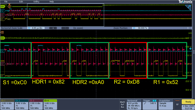
我想是在发送正常 16 位标准帧之前发送 HDR1 (0x82、器件= 3) 和 HDR2 (0x80)。 我是否认为我总共将发送 48 位数据(3 x 16 但帧:HDR1、HDR2 和数据)是正确的?

我不确定的部分是器件寻址、因为 HDR1 包含菊花链中外围器件总数的信息。 但我不确定消息流中的哪个位置可以定义哪个设备执行的操作。 希望您能有所帮助。   

感谢你能抽出时间。

  • 请注意,本文内容源自机器翻译,可能存在语法或其它翻译错误,仅供参考。如需获取准确内容,请参阅链接中的英语原文或自行翻译。

    轻微的灯泡时刻。 仔细查看数据表: 图 7-11. 菊花链 SPI 操作


    这里基于实际上的三个器件。 因此、例如、如果我想读取 STATUS1 寄存器 0x02、则 SPI 数据流如下所示:

    0x83 0x80 0x40 0x02 0x00 0x00 0x00 0x00 (HDR1、HDR2、A3、A2、A1、D3、D2、D1)

  • 请注意,本文内容源自机器翻译,可能存在语法或其它翻译错误,仅供参考。如需获取准确内容,请参阅链接中的英语原文或自行翻译。

    您好 Ben、

    对迟来的答复表示歉意。 我们没有可用的代码示例、 下面是 专门使用 MSP430 发送菊花链 SPI 命令的粗略示例代码。 我们还有一个文档介绍了菊花链、其中提供了更详细的信息、以防这很有用: 串行外设接口的菊花链实现(修订版 A)

    您的最后一个帖子的结构正确。 该结构为  (HDR1、HDR2、A3、A2、A1、D3、D2、D1)。 以 2 个器件为例、如果我们想将 0x38 写入器件 1 的 CONFIG2 (0xB) 和 0x78 写入器件 2 的 CONFIG2 (0xB)、则整个 SPI 事务将为: 0x82、0x80、0x0B、0x0B、0x78、 0x38

    对于另一个示例、下面是以菊花链配置连接的 DRV8143 和 DRV845 的菊花链通信、该命令用于读取两个器件的 DEVICE_ID 寄存器。

    void main(void)
    {
        // Initialize MCU peripherals
        initMcu();
    
        // Wake up device from sleep mode
        set_DRVOFF_hi;
        set_nSLEEP_hi;
        __delay_cycles(16000); // 1ms delay for wake-up
    
        spi_custom_daisy_chain(0x82A0, 0x0808, 0x0909);
        spi_custom_daisy_chain(0x82A0, 0x4040, 0x0000);
        spi_custom_daisy_chain(0x82A0, 0x0909, 0x0C0C);
        spi_custom_daisy_chain(0x82A0, 0x0A0A, 0x9090);
        spi_custom_daisy_chain(0x82A0, 0x0B0B, 0x3878);
        spi_custom_daisy_chain(0x82A0, 0x0C0C, 0x8484);
        spi_custom_daisy_chain(0x82A0, 0x0D0D, 0x4444);
       
        while (1){
    
        }
    }
    
    uint16_t spi_custom_daisy_chain(uint16_t header, uint16_t address, uint16_t data){
        volatile uint16_t reg_value = 0;
        reg_value = header;
        P2OUT &= ~nSCS; /*SPI set*/
    
        //transmit the header
        while (!(IFG2 & UCB0TXIFG))
            ; /* USCI_B0 TX buffer ready?*/
    
        UCB0TXBUF = (uint8_t) ((reg_value >> 8) & 0xFF);                 // Transmit first Byte,MSB-Byte
    
        while (!(IFG2 & UCB0TXIFG))
            ; /* USCI_B0 TX buffer ready*/
    
        UCB0TXBUF = (uint8_t) (reg_value & 0xFF);                        // Transmit Second Byte, LSB-Byte
    
        reg_value = address;
    
        while (!(IFG2 & UCB0TXIFG))
            ; /* USCI_B0 TX buffer ready?*/
    
        UCB0TXBUF = (uint8_t) ((reg_value >> 8) & 0xFF);                 // Transmit first Byte,MSB-Byte
    
        while (!(IFG2 & UCB0TXIFG))
            ; /* USCI_B0 TX buffer ready*/
    
        UCB0TXBUF = (uint8_t) (reg_value & 0xFF);                        // Transmit Second Byte, LSB-Byte 
    
        reg_value = data;
    
        while (!(IFG2 & UCB0TXIFG))
            ; /* USCI_B0 TX buffer ready?*/
    
        UCB0TXBUF = (uint8_t) ((reg_value >> 8) & 0xFF);                 // Transmit first Byte,MSB-Byte
    
        while (!(IFG2 & UCB0TXIFG))
            ; /* USCI_B0 TX buffer ready*/
    
        UCB0TXBUF = (uint8_t) (reg_value & 0xFF);                        // Transmit Second Byte, LSB-Byte 
    
        while (UCB0STAT & SPI_BUSY_FLAG)
        {
            ;                                                            // Wait till Transmission is complete
        }
    
        P2OUT |= nSCS; /*SPI Reset*/
        _delay_cycles(10);
    
        return 0;    
    }