This thread has been locked.

If you have a related question, please click the "Ask a related question" button in the top right corner. The newly created question will be automatically linked to this question.

[参考译文] MSP430FR2155:从应用代码中在 I2C 模式下设置 BSL

Guru**** 2361250 points
Other Parts Discussed in Thread: MSP-FET
请注意,本文内容源自机器翻译,可能存在语法或其它翻译错误,仅供参考。如需获取准确内容,请参阅链接中的英语原文或自行翻译。

https://e2e.ti.com/support/microcontrollers/msp-low-power-microcontrollers-group/msp430/f/msp-low-power-microcontroller-forum/1529233/msp430fr2155-setting-up-bsl-in-i2c-mode-from-application-code

器件型号:MSP430FR2155
主题中讨论的其他器件:MSP-FET

工具/软件:

您好:

我想测试我的器件是否正确进入 BSL 模式、以及我使用的序列通常是否正确。
我在应用中添加了这段代码:

                sc_stop(); Turns off ADC
                __disable_interrupt(); // disable interrupts
                ((void (*)())0x1000)(); // jump to BSL


然后、我要在 I2C 模式下使用 MSF_FET、并尝试使用以下脚本访问 BSL:
LOG
MODE FRxx I2C 100000 COM10
DELAY 2000
//gives wrong password to do mass erase
RX_PASSWORD pass32_wrong.txt
//
//add delay after giving wrong password
//because the device does not give
//any response after wrong password applied
//
DELAY 2000
RX_PASSWORD pass32_default.txt


我将 MSP-FET 的后端 UART 引脚连接到器件的 I2C。 还连接了接地端和 VCC 目标。
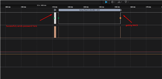
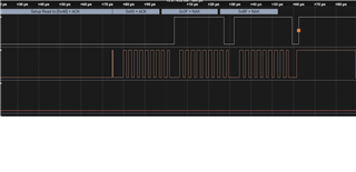
我在 I2C 线路上没有获得 ACK 响应。

我的顺序是正确的还是我做了错误的事情?

  • 请注意,本文内容源自机器翻译,可能存在语法或其它翻译错误,仅供参考。如需获取准确内容,请参阅链接中的英语原文或自行翻译。

    您好:Serg、
    您需要使用 MSP-FET 的 I2C 线路、而不是 UART 线路。

    此致、

    Diego Abad

  • 请注意,本文内容源自机器翻译,可能存在语法或其它翻译错误,仅供参考。如需获取准确内容,请参阅链接中的英语原文或自行翻译。

    嗨、是的。 我想我使用的是正确的。 我错误地将它们称为 UART 线、因为 I2C 隐藏了它们。
    我使用 MSP-FET 的 JTAG 目标连接器中的引脚 10 和 12。

  • 请注意,本文内容源自机器翻译,可能存在语法或其它翻译错误,仅供参考。如需获取准确内容,请参阅链接中的英语原文或自行翻译。

    您好:Serg、
    您是对的、这些是正确的引脚。 您能分享 I2C 通信的波形吗? 我想看看、看看是否出现了问题。 此外、您能否在应用中共享代码中实现 I2C 通信的部分?

    此致、

    Diego Abad

  • 请注意,本文内容源自机器翻译,可能存在语法或其它翻译错误,仅供参考。如需获取准确内容,请参阅链接中的英语原文或自行翻译。

    嘿、所以昨天我做了几个测试。 基本上、我发现当我尝试通过 BSL 进行硬件调用来进入 I2C BSL 时、I2C BSL 是正常工作的。 我删除了 I2C 初始化代码进行测试。 然后、我启用了从应用程序跳转到 BSL(I2C 仍然未初始化)。 删除了 MSP-FET 和器件之间的 TST 和 RST 连接、并重试。 这一次它不会为启动序列 0x48 提供 ACK。 我认为这表明 I2C 总体上可以工作、但有些情况是通过从应用激活 BSL。

  • 请注意,本文内容源自机器翻译,可能存在语法或其它翻译错误,仅供参考。如需获取准确内容,请参阅链接中的英语原文或自行翻译。

    我发现了一个问题。 它从引导加载程序跳转到 NMI_ISR()。  
    我在设置中使用了外部振荡器。 因此、我禁用了振荡器故障中断并在跳转到 BSL 之前清除了标志。
    似乎现在它保留在 BSL 中、我在尝试进行通信时收到了一些响应、但随后它卡滞。
    我禁用了现在初始化外设的所有代码、仍然存在相同的问题。
    以下是代码示例:

     // Stop Watchdog Timer. TODO: implement WDG
        MAP_WDT_A_hold(WDT_A_BASE);
    
        MAP_GPIO_setAsInputPinWithPullUpResistor(GPIO_PORT_P1, (GPIO_PIN_ALL8 & ~(GPIO_PIN0 + GPIO_PIN1 + GPIO_PIN2 + GPIO_PIN3)));
        MAP_GPIO_setAsInputPinWithPullUpResistor(GPIO_PORT_P2, GPIO_PIN_ALL8);
        MAP_GPIO_setAsInputPinWithPullUpResistor(GPIO_PORT_P3, GPIO_PIN_ALL8);
        MAP_GPIO_setAsInputPinWithPullUpResistor(GPIO_PORT_P4, GPIO_PIN_ALL8);
        MAP_GPIO_setAsOutputPin(GPIO_PORT_PJ, GPIO_PIN_ALL8);
        MAP_GPIO_setOutputLowOnPin(GPIO_PORT_PJ, GPIO_PIN_ALL8);
    
        // UART RX and TX lines (P4.2 & P4.3)
        // Disable UART module before setting these pins as outputs if UART is not used
        MAP_GPIO_setAsOutputPin(GPIO_PORT_P4, GPIO_PIN2 + GPIO_PIN3);
        MAP_GPIO_setOutputLowOnPin(GPIO_PORT_P4, GPIO_PIN2 + GPIO_PIN3);
    
        clock_init();
    
        LOG_DEBUG_INIT();
    
        /*
         * Disable the GPIO power-on default high-impedance mode to activate
         * previously configured port settings
         */
        MAP_PMM_unlockLPM5();
    
        __enable_interrupt();
    
        while (1)
        {
            next_state = ctl_process(); // Doesn't go furter for this example


    clock_init 的代码:
    /**
     * Initializes clock sources for the device.
     * Uses an external clock source for ACLK and DCO for SMCLK and MCLK.
     */
    static void clock_init(void)
    {
        // Configure Pins for XIN and XOUT
        //Set P2.6 and P2.7 as Module Function Input.
        MAP_GPIO_setAsPeripheralModuleFunctionInputPin(
        	GPIO_PORT_P2,
        	GPIO_PIN6 + GPIO_PIN7,
        	GPIO_SECONDARY_MODULE_FUNCTION
        );
    
        //Initializes the XT1 crystal oscillator with no timeout
        //In case of failure, code hangs here.
        //For time-out instead of code hang use CS_turnOnXT1LFWithTimeout()
        MAP_CS_turnOnXT1LF(CS_XT1_DRIVE_0);
        // Initialize the external clock source
        MAP_CS_setExternalClockSource(XT1CLK_FREQUENCY);
    
        // Set the ACLK to use the external clock source (XT1CLK)
        MAP_CS_initClockSignal(CS_ACLK, CS_XT1CLK_SELECT, CS_CLOCK_DIVIDER_1);
    
        // Below settings for different clock speed
        // //Set DCO FLL reference = REFO
        // CS_initClockSignal(
        //     CS_FLLREF,
        //     CS_XT1CLK_SELECT,
        //     CS_CLOCK_DIVIDER_1
        //     );
    
        // CS_initFLL(CS_MCLK_DESIRED_FREQUENCY_IN_KHZ, CS_MCLK_FLLREF_RATIO);
    
    	//clear all OSC fault flag
    	MAP_CS_clearAllOscFlagsWithTimeout(1000);
    
    	//Enable oscillator fault interrupt
        MAP_SFR_enableInterrupt(SFR_OSCILLATOR_FAULT_INTERRUPT);
    
        // Set SMCLK = DCO with frequency divider of 1
        MAP_CS_initClockSignal(CS_SMCLK, CS_DCOCLKDIV_SELECT, CS_CLOCK_DIVIDER_1);
        // Set MCLK = DCO with frequency divider of 1
        MAP_CS_initClockSignal(CS_MCLK, CS_DCOCLKDIV_SELECT, CS_CLOCK_DIVIDER_1);
    }


    ctl_process () 的代码:
    ctl_process_result_t ctl_process(void) {
        ctl_process_result_t process_result = CTL_PROCESS_NEXT;
        switch (current_state) {
            case INIT:
                // sc_start();
                current_state++;
                break;
            case OPERATING:
                LOG_INFO_MSG("OPERATING");
                // process_operating();
                if (current_state == OPERATING)
                {
    //                sc_stop(); // Turn off ADC
    //                dpt_ctl_deinit(); // Deinitialize the dpt control
                    __disable_interrupt(); // disable interrupts
    
                    MAP_SFR_disableInterrupt(SFR_OSCILLATOR_FAULT_INTERRUPT);
                    MAP_CS_clearAllOscFlagsWithTimeout(1000);
                    DELAY_MS(5);
                    ((void (*)())0x1000)(); // jump to BSL
                    
                }


    使用 BSL 与以下命令:
    C:\ti\BSL-Scripter\BSL-Scripter.exe -d -i [COM10,I2C,100000] -n FRxx -b .\ScriptExampleWindows\FRxx_i2c\pass32_default.txt
    Verbose is turned on!
    Device : FRxx
    Init communication parameters : [COM10,I2C,100000]
    RX_PASSWORD .\ScriptExampleWindows\FRxx_i2c\pass32_default.txt
            Read Txt File  : C:\ti\BSL-Scripter\ScriptExampleWindows/FRxx_i2c/pass32_default.txt
            [80] [21] [00] [11] [ff] [ff] [ff] [ff] [ff] [ff] [ff] [ff] [ff] [ff] [ff] [ff]
            [ff] [ff] [ff] [ff] [ff] [ff] [ff] [ff] [ff] [ff] [ff] [ff] [ff] [ff] [ff] [ff]
            [ff] [ff] [ff] [ff] [9e] [e6]
    
    PS C:\ti\BSL-Scripter>

    它应响应错误:错误的密码。

    LA 的 I2C 行为:


     放大的 NACK 行为:

  • 请注意,本文内容源自机器翻译,可能存在语法或其它翻译错误,仅供参考。如需获取准确内容,请参阅链接中的英语原文或自行翻译。

    您好:Serg、
    我建议尝试 MSP430 SDK 示例 I2C BSL、并看看它是否有任何区别。 此外、您是否可以使用外部上拉电阻器?

    此致、

    Diego Abad

  • 请注意,本文内容源自机器翻译,可能存在语法或其它翻译错误,仅供参考。如需获取准确内容,请参阅链接中的英语原文或自行翻译。

    您能引用这个例子吗? 我在 SDK 中找不到任何 MSP430 器件的示例。 我使用 MSP430 Ware v  3.80.14.01 检查是否为 Resource Explorer CCS。

  • 请注意,本文内容源自机器翻译,可能存在语法或其它翻译错误,仅供参考。如需获取准确内容,请参阅链接中的英语原文或自行翻译。

    您好:Serg、
    它应该位于 MSP430 SDK 内的 boot_loader 文件夹中。 我还建议查看 MSP430 FRAM 器件引导加载程序 (BSL)  

    此致、

    Diego Abad

  • 请注意,本文内容源自机器翻译,可能存在语法或其它翻译错误,仅供参考。如需获取准确内容,请参阅链接中的英语原文或自行翻译。

    “嘿嘿,我知道啦! MSP-FET 未置于 BSL 模式。 以波特率 9620 打开后端 UART 端口、然后使用 BSL 脚本程序工作。 让我最困惑的是、在使用硬件调用方法时、在不激活 BSL 的情况下它是如何工作的。