This thread has been locked.

If you have a related question, please click the "Ask a related question" button in the top right corner. The newly created question will be automatically linked to this question.

[参考译文] MSP430FR6889:通过 UART FTDI 适配器进行通信

Guru**** 2378650 points
请注意,本文内容源自机器翻译,可能存在语法或其它翻译错误,仅供参考。如需获取准确内容,请参阅链接中的英语原文或自行翻译。

https://e2e.ti.com/support/microcontrollers/msp-low-power-microcontrollers-group/msp430/f/msp-low-power-microcontroller-forum/1125384/msp430fr6889-communicating-over-uart-ftdi-adaptor

器件型号:MSP430FR6889

您好!

我正在尝试根据从不同论坛帖子收集的少量信息和一些示例代码编写一个程序。 此时、我可以通过 UART 直接发送 ASCII 值、但如果我使用"printf"函数、则不会发生任何情况。 最后、我想通过 UART 发送一些传感器数据。 如果有人能帮助我解决这个问题、我将不胜感激。 以下是我的代码:

#include <msp430.h>
#include "driverlib.h"
#include "NcApi.h"
#include "NeoParser.h"
#include "DSPLib.h"
#include <gpio.h>
#include <intrinsics.h> //
#include <stdint.h> //
#include <stdio.h> //


#define ENABLE_PINS     0xFFFE      // Required to use inputs and outputs
#define UART_CLK_SEL    0x0080      // Specifies accurate clock for UART peripheral
#define BR0_FOR_9600    0x34        // Value required to use 9600 baud
#define BR1_FOR_9600    0x00        // Value required to use 9600 baud
#define CLK_MOD         0x4911      // Microcontroller will "clean-up" clock signal
#define ACLK            0x0100      // Timer_A SMCLK source
#define UP              0x0010      // Timer_A UP mode

volatile int receiveData = 0;

void select_clock_signals(void);    // Assigns microcontroller clock signals
void assign_pins_to_uart(void);     // P4.2 is for TXD, P4.3 is for RXD
void use_9600_baud(void);           // UART operates at 9600 bits/second
void enable_TA0CTL(void);           // Enable the timer 0 counter
void set_timer0_count(int);

int main(void)
{
    WDTCTL = WDTPW | WDTHOLD;       // Stop WDT
    PM5CTL0 = ENABLE_PINS;          // Enable pins

    select_clock_signals();         // Assigns microcontroller clock signals
    assign_pins_to_uart();          // P4.2 is for TXD, P4.3 is for RXD
    use_9600_baud();                // UART operates at 9600 bits/second
    enable_TA0CTL();


    UCA0IE = UCRXIE;                // Enable RX interupt
    _BIS_SR(GIE);                   // Activate enabled UART RXD interrupt


    while(1)                      
    {
        static const int a=10;

            //UCA0TXBUF = 0x55;       // Send 0x55 out of P4.2
            printf("Reading samples\n");
            //printf("Reading samples %u\n",a);
    }
}

//*********************************************************************************
//* UART Interrupt Service Routine *
//* This is the ISR for both the TX interrupt and the RX interrupt *
//*********************************************************************************
#pragma vector=USCI_A0_VECTOR
__interrupt void UART_ISR(void)
{
    UCA0IFG = UCA0IFG & (~UCRXIFG); // Clear RX Interrupt FlaG
}
//*********************************************************************************
//* Select Clock Signals *
//*********************************************************************************
void select_clock_signals(void)
{
    CSCTL0 = 0xA500; // "Password" to access clock calibration registers
    CSCTL1 = 0x0046; // Specifies frequency of main clock
    CSCTL2 = 0x0133; // Assigns additional clock signals
    CSCTL3 = 0x0000; // Use clocks at intended frequency, do not slow them down
}
//*********************************************************************************
//* Used to Give UART Control of Appropriate Pins *
//*********************************************************************************
void assign_pins_to_uart(void)
{
    P4SEL1 = 0x00; // 0000 0000
    P4SEL0 = BIT3 | BIT2; // 0000 1100
    // ^^
    // ||
    // |+---- 01 assigns P4.2 to UART Transmit (TXD)
    // |
    // +----- 01 assigns P4.3 to UART Receive (RXD)
}
//*********************************************************************************
//* Specify UART Baud Rate *
//*********************************************************************************
void use_9600_baud(void)
{
    UCA0CTLW0 = UCSWRST; // Put UART into SoftWare ReSeT
    UCA0CTLW0 = UCA0CTLW0 | UART_CLK_SEL; // Specifies clock source for UART
    UCA0BR0 = BR0_FOR_9600; // Specifies bit rate (baud) of 9600
    UCA0BR1 = BR1_FOR_9600; // Specifies bit rate (baud) of 9600
    UCA0MCTLW = CLK_MOD; // "Cleans" clock signal
    UCA0CTLW0 = UCA0CTLW0 & (~UCSWRST); // Takes UART out of SoftWare ReSeT
}

void enable_TA0CTL(void)
{
    TA0CTL = ACLK | UP;             // Set ACLK, UP MODE
    TA0CCTL0 = CCIE;                // Enable interrupt for Timer_0
}
void set_timer0_count(int x)
{
    TA0CCR0 = x;                        //Used to set the timer0 counter
}

如果我取消注释第 48行和 第49行、串行终端上没有显示任何内容。 它仅在我取消注释第47行和注释 第48和49行时起作用。

谢谢。  

  • 请注意,本文内容源自机器翻译,可能存在语法或其它翻译错误,仅供参考。如需获取准确内容,请参阅链接中的英语原文或自行翻译。

    Iftekar、您好!  

    默认情况下,printf()不会通过 UART 输出数据。

    如果您注释掉第47行、则此处未将数据加载到 UART TX 缓冲区、因此除非该行已就位、否则您不会看到任何 UART 流量。 在主题的其他一些线程中,用户通过覆盖 fputc()和 fput() 函数来重定向 printf()输出。

    编辑:只需添加指向我们有关使用 printf()的 CCS 文档的链接: https://software-dl.ti.com/ccs/esd/documents/sdto_cgt_tips_for_using_printf.html


    此致、
    Brandon Fisher

  • 请注意,本文内容源自机器翻译,可能存在语法或其它翻译错误,仅供参考。如需获取准确内容,请参阅链接中的英语原文或自行翻译。

    您好 、Brandon、

    感谢你的答复。 我实际上不是在尝试通过 UART 向 CCS 发送数据。 我 已将 P4.2和 P4.3配置为 UART TX/RX、并已将 FTDI 板连接到该板、我正在使用该 FTDI 板的 COM 端口读取 Putty 等串行终端上的 UART 数据。  

    在发布问题后、我曾做过一些事情、我写了一个简短的代码来通过 FTDI UART 发送数据。 它解决了我的一半问题。 现在、我可以通过它发送一个字符串、但我无法使用它发送初始值、例如从传感器收集的 ADC 值。 以下是函数:

    void UART_transmitString( char *pStr ) //Transmits a string over UART0
    {
        while( *pStr )
        {
            while(!(UCA0IFG&UCTXIFG));
            UCA0TXBUF = *pStr;
            pStr++;
        }
    }

    因此、如果我对第47行进行注释、然后 将 第48行和第49行替换为以下两行:

               UART_transmitString("Reading samples\n");
               UART_transmitString("Reading samples %u\n", a);

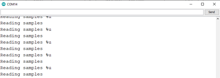
    我在串行终端中持续接收这两条线路:


    那么、我的 UART 通信工作正常。 很明显、由于我没有在 该函数中实现任何函数来发送该整数"A"、因此我不会收到它。 您对如何修改此函数以发送字符串以及 整数、浮点、长整型等值是否有任何建议?  

    如果我可以使其正常工作、那么我完全不必使用 printf。

    谢谢。

  • 请注意,本文内容源自机器翻译,可能存在语法或其它翻译错误,仅供参考。如需获取准确内容,请参阅链接中的英语原文或自行翻译。

    Iftekhar、您好!

    如果您真的想重新创建 printf 的所有格式功能 、可以查看 vfprintf 的 C 标准库中的源代码:http://sourceware.org/git/?p=glibc.git;a=blob;f=stdio-common/vfprintf.c;h=fc370e8cbc4e9652a2ed377b1c6f2324f15b1bf9;hb=3321010338384ecdc6633a8b032bb0ed6aa9b19a

    如果您想要更简单的方法,只需检查*pStr 的'%'字符,然后在*(pStr +1)查找格式标记,即可开始在此处进行处理,以便您知道在哪里打印参数。  

    在这里、您可以 找到有关如何实现函数( 如 itoa (将 int 转换为 string)的大量在线教程、这些教程有助于您将 int 作为字符加载到传输缓冲区、以便于读取。  

    此致、
    Brandon Fisher

  • 请注意,本文内容源自机器翻译,可能存在语法或其它翻译错误,仅供参考。如需获取准确内容,请参阅链接中的英语原文或自行翻译。

    您好、Brandon、再次感谢。 最后、我让它正常工作。 我将数字转换为字符串。 但是、现在看起来每隔几个字节发送一次数据、UART 的延迟为36到40ms。 我不确定它为什么这么做。 我正在使用串行终端将数据可视化。 是否有解决问题的建议?

    #include <msp430.h>
    #include "driverlib.h"
    #include <gpio.h>
    #include <intrinsics.h> //
    #include <stdint.h> //
    #include <stdio.h> //
    #include "stdarg.h"
    
    
    #define ENABLE_PINS     0xFFFE      // Required to use inputs and outputs
    #define UART_CLK_SEL    0x0080      // Specifies accurate clock for UART peripheral
    #define BR0_FOR_9600    0x34        // Value required to use 9600 baud
    #define BR1_FOR_9600    0x00        // Value required to use 9600 baud
    #define CLK_MOD         0x4911      // Microcontroller will "clean-up" clock signal
    #define ACLK            0x0100      // Timer_A SMCLK source
    #define UP              0x0010      // Timer_A UP mode
    
    volatile int receiveData = 0;
    
    void select_clock_signals(void);    // Assigns microcontroller clock signals
    void assign_pins_to_uart(void);     // P4.2 is for TXD, P4.3 is for RXD
    void use_9600_baud(void);           // UART operates at 9600 bits/second
    void enable_TA0CTL(void);           // Enable the timer 0 counter
    void set_timer0_count(int);
    void UART_transmitString();
    
    
    void print(char *text)
    {
        unsigned int i = 0;
        while(text[i] != '\0')
        {
            while (!(UCA0IFG&UCTXIFG));      // Check if TX is ongoing
            UCA0TXBUF = text[i];            // TX -> Received Char + 1
            i++;
        }
    }
    
    void printNumber(unsigned int num)
    {
        char buf[6];
        char *str = &buf[5];
    
        *str = '\0';
    
        do
        {
            unsigned long m = num;
            num /= 10;
            char c = (m - 10 * num) + '0';
            *--str = c;
        } while(num);
    
        print(str);
    }


    int main(void)
    {
        WDTCTL = WDTPW | WDTHOLD;       // Stop WDT
        PM5CTL0 = ENABLE_PINS;          // Enable pins
    
        select_clock_signals();         // Assigns microcontroller clock signals
        assign_pins_to_uart();          // P4.2 is for TXD, P4.3 is for RXD
        use_9600_baud();                // UART operates at 9600 bits/second
        enable_TA0CTL();
    
    
        UCA0IE = UCRXIE;                // Enable RX interupt
        _BIS_SR(GIE);                   // Activate enabled UART RXD interrupt
    
        while(1)                        // Wait here unless you get UART interrupt
        {
            static const int a= 115;
               printNumber(a);
               print("\r\n");
               //count++;
    
        }
    }
    
    //*********************************************************************************
    //* UART Interrupt Service Routine *
    //* This is the ISR for both the TX interrupt and the RX interrupt *
    //*********************************************************************************
    #pragma vector=USCI_A0_VECTOR
    __interrupt void USCI0TX_ISR(void)
    {
        UCA0IFG = UCA0IFG & (~UCRXIFG); // Clear RX Interrupt FlaG
    }
    //*********************************************************************************
    //* Select Clock Signals *
    //*********************************************************************************
    void select_clock_signals(void)
    {
        CSCTL0 = 0xA500; // "Password" to access clock calibration registers
        CSCTL1 = 0x0046; // Specifies frequency of main clock
        CSCTL2 = 0x0133; // Assigns additional clock signals
        CSCTL3 = 0x0000; // Use clocks at intended frequency, do not slow them down
    }
    //*********************************************************************************
    //* Used to Give UART Control of Appropriate Pins *
    //*********************************************************************************
    void assign_pins_to_uart(void)
    {
        P4SEL1 = 0x00; // 0000 0000
        P4SEL0 = BIT3 | BIT2; // 0000 1100
        //P4.2 to TXD
        //P4.3 toRXD
    }
    //*********************************************************************************
    //* Specify UART Baud Rate *
    //*********************************************************************************
    void use_9600_baud(void)
    {
        UCA0CTLW0 = UCSWRST; // Put UART into SoftWare ReSeT
        UCA0CTLW0 = UCA0CTLW0 | UART_CLK_SEL; // Specifies clock source for UART
        UCA0BR0 = BR0_FOR_9600; // Specifies bit rate (baud) of 9600
        UCA0BR1 = BR1_FOR_9600; // Specifies bit rate (baud) of 9600
        UCA0MCTLW = CLK_MOD; // "Cleans" clock signal
        UCA0CTLW0 = UCA0CTLW0 & (~UCSWRST); // Takes UART out of SoftWare ReSeT
    }
    
    void enable_TA0CTL(void)
    {
        TA0CTL = ACLK | UP;             // Set ACLK, UP MODE
        TA0CCTL0 = CCIE;                // Enable interrupt for Timer_0
    }
    void set_timer0_count(int x)
    {
        TA0CCR0 = x;                        //Used to set the timer0 counter
    }
    
    void UART_transmitString( char *pStr ) //Transmits a string over UART0
    {
        while( *pStr )
        {
            while(!(UCA0IFG&UCTXIFG));
            UCA0TXBUF = *pStr;
            pStr++;
        }
    }
    

  • 请注意,本文内容源自机器翻译,可能存在语法或其它翻译错误,仅供参考。如需获取准确内容,请参阅链接中的英语原文或自行翻译。

    Iftekhar、您好!

    如果您使用示波器或逻辑分析仪探测 UART 线路、您是否会看到此延迟?  

    您的串行终端监控器可能每隔30-40ms 读取一次缓冲区、您实际上会 非常定期地发送该数据。

    请记住、在9600波特时、发送字符大约需要1ms、或者发送5个字符需要5ms ("115"加上返回字符和新行字符)。 您的终端程序的时间戳似乎没有反映这一点。 我认为36-40ms 就是它更新的频率。  

    此致、
    Brandon Fisher  

  • 请注意,本文内容源自机器翻译,可能存在语法或其它翻译错误,仅供参考。如需获取准确内容,请参阅链接中的英语原文或自行翻译。

    布兰登在头上打了指甲。 USB 不是瞬时的、硬件和屏幕之间有很多缓冲器。

    如果您有 FTDI 芯片、则可以部分加速该过程。 打开设备管理器、找到并展开"Ports (COM & LPT)"部分、然后双击与 FTDI-UART 适配器相对应的 USB Serial Port 条目。 在"USB Serial Port (COMx) Properties"(USB 串行端口(COMx)属性)窗口中单击"Port Settings"(端口设置)选项卡、然后单击底部附近的"Advanced..."(高级...)按钮。 将延迟计时器从16ms 更改为较低的值、例如8ms 或更低。 更改此值后、从 USB 上拔下适配器、然后重新连接、以进行良好的测量。

    COM Port Advanced Settings

  • 请注意,本文内容源自机器翻译,可能存在语法或其它翻译错误,仅供参考。如需获取准确内容,请参阅链接中的英语原文或自行翻译。

    您好 、Brandon、

    感谢您的建议。 你是对的。 我已经使用逻辑分析仪检查了 FTDI 适配器输入端的 UART 总线、看起来没有这样的延迟。 我正在通过 UART 发送加速计数据以将其可视化。 我仍然没有找到一个具有基于时域的适当 x 轴以及标记的 Poper UART 或 COM 端口示波器。 这就是我使用 Arduino IDE 串行终端的原因。 它至少在 x 轴上有以毫秒为单位的时间刻度、如果我冻结屏幕、我可以进行粗略计算以验证振动频率。 但是、我目前收到的频率值提高了10倍。 例如、如果振动频率为3Hz、我的读数为30+Hz。 在我看来、数据传输延迟是主要原因。 是否有任何方法可以减少此延迟?

    谢谢  

  • 请注意,本文内容源自机器翻译,可能存在语法或其它翻译错误,仅供参考。如需获取准确内容,请参阅链接中的英语原文或自行翻译。

    您好 Seth、

    感谢您的建议。 遗憾的是,它没有解决这个问题。 我将收到相同的延迟量。  

  • 请注意,本文内容源自机器翻译,可能存在语法或其它翻译错误,仅供参考。如需获取准确内容,请参阅链接中的英语原文或自行翻译。

    Iftekhar、您好!

    如果您想减少 UART 通信延迟、可以提高波特率。 115.2kBaud 之类的东西是一个相当标准的值、可以使理论吞吐量提高10倍以上。 因此、10字节传输所需的时间不是大约1ms、而是0.1ms。 大多数终端程序也能够支持此速率。

    当然、如果没有您看到的30-40ms 窗口、您的结果不会出现在终端侧、因为这取决于系统和资源。  

    此致、
    Brandon Fisher

  • 请注意,本文内容源自机器翻译,可能存在语法或其它翻译错误,仅供参考。如需获取准确内容,请参阅链接中的英语原文或自行翻译。

    谢谢、它看起来是唯一的选择。