请注意,本文内容源自机器翻译,可能存在语法或其它翻译错误,仅供参考。如需获取准确内容,请参阅链接中的英语原文或自行翻译。
器件型号:MSP430FR6889 您好!
我正在尝试根据从不同论坛帖子收集的少量信息和一些示例代码编写一个程序。 此时、我可以通过 UART 直接发送 ASCII 值、但如果我使用"printf"函数、则不会发生任何情况。 最后、我想通过 UART 发送一些传感器数据。 如果有人能帮助我解决这个问题、我将不胜感激。 以下是我的代码:
#include <msp430.h>
#include "driverlib.h"
#include "NcApi.h"
#include "NeoParser.h"
#include "DSPLib.h"
#include <gpio.h>
#include <intrinsics.h> //
#include <stdint.h> //
#include <stdio.h> //
#define ENABLE_PINS 0xFFFE // Required to use inputs and outputs
#define UART_CLK_SEL 0x0080 // Specifies accurate clock for UART peripheral
#define BR0_FOR_9600 0x34 // Value required to use 9600 baud
#define BR1_FOR_9600 0x00 // Value required to use 9600 baud
#define CLK_MOD 0x4911 // Microcontroller will "clean-up" clock signal
#define ACLK 0x0100 // Timer_A SMCLK source
#define UP 0x0010 // Timer_A UP mode
volatile int receiveData = 0;
void select_clock_signals(void); // Assigns microcontroller clock signals
void assign_pins_to_uart(void); // P4.2 is for TXD, P4.3 is for RXD
void use_9600_baud(void); // UART operates at 9600 bits/second
void enable_TA0CTL(void); // Enable the timer 0 counter
void set_timer0_count(int);
int main(void)
{
WDTCTL = WDTPW | WDTHOLD; // Stop WDT
PM5CTL0 = ENABLE_PINS; // Enable pins
select_clock_signals(); // Assigns microcontroller clock signals
assign_pins_to_uart(); // P4.2 is for TXD, P4.3 is for RXD
use_9600_baud(); // UART operates at 9600 bits/second
enable_TA0CTL();
UCA0IE = UCRXIE; // Enable RX interupt
_BIS_SR(GIE); // Activate enabled UART RXD interrupt
while(1)
{
static const int a=10;
//UCA0TXBUF = 0x55; // Send 0x55 out of P4.2
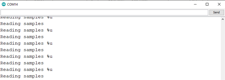
printf("Reading samples\n");
//printf("Reading samples %u\n",a);
}
}
//*********************************************************************************
//* UART Interrupt Service Routine *
//* This is the ISR for both the TX interrupt and the RX interrupt *
//*********************************************************************************
#pragma vector=USCI_A0_VECTOR
__interrupt void UART_ISR(void)
{
UCA0IFG = UCA0IFG & (~UCRXIFG); // Clear RX Interrupt FlaG
}
//*********************************************************************************
//* Select Clock Signals *
//*********************************************************************************
void select_clock_signals(void)
{
CSCTL0 = 0xA500; // "Password" to access clock calibration registers
CSCTL1 = 0x0046; // Specifies frequency of main clock
CSCTL2 = 0x0133; // Assigns additional clock signals
CSCTL3 = 0x0000; // Use clocks at intended frequency, do not slow them down
}
//*********************************************************************************
//* Used to Give UART Control of Appropriate Pins *
//*********************************************************************************
void assign_pins_to_uart(void)
{
P4SEL1 = 0x00; // 0000 0000
P4SEL0 = BIT3 | BIT2; // 0000 1100
// ^^
// ||
// |+---- 01 assigns P4.2 to UART Transmit (TXD)
// |
// +----- 01 assigns P4.3 to UART Receive (RXD)
}
//*********************************************************************************
//* Specify UART Baud Rate *
//*********************************************************************************
void use_9600_baud(void)
{
UCA0CTLW0 = UCSWRST; // Put UART into SoftWare ReSeT
UCA0CTLW0 = UCA0CTLW0 | UART_CLK_SEL; // Specifies clock source for UART
UCA0BR0 = BR0_FOR_9600; // Specifies bit rate (baud) of 9600
UCA0BR1 = BR1_FOR_9600; // Specifies bit rate (baud) of 9600
UCA0MCTLW = CLK_MOD; // "Cleans" clock signal
UCA0CTLW0 = UCA0CTLW0 & (~UCSWRST); // Takes UART out of SoftWare ReSeT
}
void enable_TA0CTL(void)
{
TA0CTL = ACLK | UP; // Set ACLK, UP MODE
TA0CCTL0 = CCIE; // Enable interrupt for Timer_0
}
void set_timer0_count(int x)
{
TA0CCR0 = x; //Used to set the timer0 counter
}
如果我取消注释第 48行和 第49行、串行终端上没有显示任何内容。 它仅在我取消注释第47行和注释 第48和49行时起作用。
谢谢。