请注意,本文内容源自机器翻译,可能存在语法或其它翻译错误,仅供参考。如需获取准确内容,请参阅链接中的英语原文或自行翻译。
器件型号:MSP430FR6989 您好!
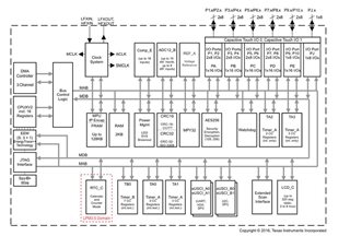
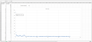
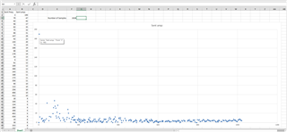
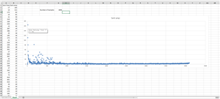
我使用的是 MSP430FR6989和 BMI160 IMU (Sensors BoosterPack)。 它们通过 I2C 进行通信。 我正在测量 Z 轴加速度、并尝试对接收到的数据执行 FFT。 我有一个以3.5Hz 频率振动的测试平台。 我将使用 DSPLIB.h 中的 FFT 函数 FFT 完成后、我将获取幅值最小时的前5个 FFT 值并将其显示在终端上、但我始终会获得随机频率值。 由于我不是 FFT 算法方面的专家、我不确定我做了什么错误。 如果有人能就如何解决这个问题提出一些建议、我将不胜感激。
谢谢你。
以下是我的代码:
#include <msp430.h>
#include "driverlib.h"
#include "DSPLib.h"
#include <gpio.h>
#include <intrinsics.h>
#include <msp430fr5xx_6xxgeneric.h>
#include <stdint.h>
#include <stdio.h>
//new
//#include "myClocks.h"
//new
//******************************************************************************
// Defines *********************************************************************
//******************************************************************************
//Address if the BMI160
#define SLAVE_ADDR 0x69
//Maximum I2C buffer size
#define MAX_BUFFER_SIZE 20
//Number of FFT samples
#define SAMPLES 4096
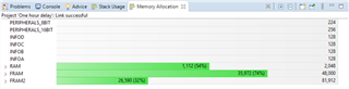
/* Declare as persistent to move variable from RAM to FRAM */
#pragma PERSISTENT(input)
int16_t input[SAMPLES] = {0}; //Store samples
#pragma PERSISTENT(max)
int16_t max[SAMPLES] = {0}; //Store frequencies with maximum amplitudes
#pragma PERSISTENT(amp)
int16_t amp[SAMPLES] = {0}; //Store the maximum amplitudes
/* Temporary data array for processing */
DSPLIB_DATA(temp,4)
/* Declare as persistent to move variable to FRAM */
#pragma PERSISTENT(temp)
int16_t temp[3*SAMPLES/2] = {0};
//Global flags for sensor interrupts to avoid interrupt nesting
volatile int motion_trigger = 0;
/* Benchmark cycle counts */
volatile uint32_t cycleCount;
//new
#define UP 0x0010 // Timer_A Up mode
#define CONTINUOUS 0x0020 // Timer_A Continuous mode
#define ACLK 0x0100 // Timer_A SMCLK source
#define DEVELOPMENT 0x5A80 // Stop the watchdog timer
#define BOUNCE_DELAY 0xA000 // Delay for Button Bounce
#define MS_10 400 // Approximate value to count for 10ms
#define SMCLK 0x0200 // Timer_A SMCLK source
//new
//******************************************************************************
// Frequency Functions *********************************************************
//******************************************************************************
void bubbleSort(int amp[], int max[], int n)
{
int i, j, temp;
for (i = 0; i < n-1; i++)
{
// Last i elements are already in place
for (j = 0; j < n-i-1; j++)
{
if (amp[j] < amp[j+1])
{
temp = max[j];
max[j] = max[j+1];
max[j+1] = temp;
temp = amp[j];
amp[j] = amp[j+1];
amp[j+1] = temp;
}
}
}
}
void getMaximums(int16_t input[], int samples, int16_t max[], int16_t amp[])
{
int i,j = 0;
for(i=1; i<samples-1; i++)
{
if((input[i-1] < input[i]) && (input[i] > input[i+1]))
{
amp[j] = input[i];
max[j++] = i;
}
}
bubbleSort(amp, max, samples);
}
//******************************************************************************
// Timer Functions *************************************************************
//******************************************************************************
int delay(int count)
{
if(TA1CTL & TAIFG) // If Timer_1 is done counting
{
count = count-1; // Decrement count
TA1CTL = TA1CTL & (~TAIFG); // Reset Timer_1
}
return count; // Return the value of count
} // end delay
//******************************************************************************
// UART Functions **************************************************************
//******************************************************************************
void UART_transmitString( char *pStr ) //Transmits a string over UART0
{
while( *pStr )
{
while(!(UCA0IFG&UCTXIFG));
UCA0TXBUF = *pStr;
pStr++;
}
}
//******************************************************************************
// I2C Functions ***************************************************************
//******************************************************************************
typedef enum I2C_ModeEnum{
IDLE_MODE,
NACK_MODE,
TX_REG_ADDRESS_MODE,
RX_REG_ADDRESS_MODE,
TX_DATA_MODE,
RX_DATA_MODE,
SWITCH_TO_RX_MODE,
SWITHC_TO_TX_MODE,
TIMEOUT_MODE
} I2C_Mode;
/* Used to track the state of the software state machine*/
I2C_Mode MasterMode = IDLE_MODE;
uint8_t TransmitRegAddr = 0; //Register address for transmission
uint8_t ReceiveBuffer[MAX_BUFFER_SIZE] = {0}; //Buffer for received values
uint8_t RXByteCtr = 0; //Count received bytes
uint8_t ReceiveIndex = 0; //Index of received data
uint8_t TransmitBuffer[MAX_BUFFER_SIZE] = {0}; //Buffer for transmitted values
uint8_t TXByteCtr = 0; //Count transmitted bytes
uint8_t TransmitIndex = 0; //Index of transmitted data
void CopyArray(uint8_t *source, uint8_t *dest, uint8_t count)
{
uint8_t copyIndex = 0;
for (copyIndex = 0; copyIndex < count; copyIndex++)
{
dest[copyIndex] = source[copyIndex];
}
}
I2C_Mode I2C_Master_ReadReg(uint8_t dev_addr, uint8_t reg_addr, uint8_t count)
{
//printf("R\n");
/* Initialize state machine */
MasterMode = TX_REG_ADDRESS_MODE;
TransmitRegAddr = reg_addr;
RXByteCtr = count;
TXByteCtr = 0;
ReceiveIndex = 0;
TransmitIndex = 0;
/* Initialize slave address and interrupts */
UCB1I2CSA = dev_addr;
UCB1IFG &= ~(UCTXIFG + UCRXIFG); // Clear any pending interrupts
UCB1IE &= ~UCRXIE; // Disable RX interrupt
UCB1IE |= UCTXIE; // Enable TX interrupt
UCB1CTLW0 |= UCTR + UCTXSTT; // I2C TX, start condition
__bis_SR_register(LPM0_bits + GIE); // Enter LPM0 w/ interrupts
// UCB1IE &= ~UCRXIE; // Disable RX interrupt
return MasterMode;
}
I2C_Mode I2C_Master_WriteReg(uint8_t dev_addr, uint8_t reg_addr, uint8_t *reg_data, uint8_t count)
{
/* Initialize state machine */
MasterMode = TX_REG_ADDRESS_MODE;
TransmitRegAddr = reg_addr;
//Copy register data to TransmitBuffer
CopyArray(reg_data, TransmitBuffer, count);
TXByteCtr = count;
RXByteCtr = 0;
ReceiveIndex = 0;
TransmitIndex = 0;
/* Initialize slave address and interrupts */
UCB1I2CSA = dev_addr;
UCB1IFG &= ~(UCTXIFG + UCRXIFG); // Clear any pending interrupts
UCB1IE &= ~UCRXIE; // Disable RX interrupt
UCB1IE |= UCTXIE; // Enable TX interrupt
UCB1CTLW0 |= UCTR + UCTXSTT; // I2C TX, start condition
__bis_SR_register(LPM0_bits + GIE); // Enter LPM0 w/ interrupts
//printf("W\n");
return MasterMode;
}
//******************************************************************************
// BMI160 Functions ************************************************************
//******************************************************************************
void bmi160_init(char FOC_axis)
{
uint8_t writeData[1];
//Read Chip ID, which is D1
I2C_Master_ReadReg(SLAVE_ADDR, 0x00, 1);
if(ReceiveBuffer[0] != 0xD1)
{
UART_transmitString(" Incorrect sensor chip ID ");
printf("Incorrect sensor chip ID\n");
}
//Configure the accelerometer
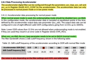
writeData[0]=0b00101100; //Set acc_us to 0 for off, and acc_bwp must then be 010. Set acc_odr to 1011(800Hz),1100(1600Hz),1000(100Hz),0001(25/32Hz)
I2C_Master_WriteReg(SLAVE_ADDR, 0x40, writeData, 1);
//Check if configuration worked
I2C_Master_ReadReg(SLAVE_ADDR, 0x40, 1);
if(ReceiveBuffer[0] != writeData[0])
{
UART_transmitString(" Accelerometer config failed ");
printf("Accelerometer config failed\n");
}
//Set the range of the accelerometer
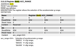
writeData[0]=0b1000; //0b0011 for 2g, 0b0101 for 4g, 0b1000 for 8g
I2C_Master_WriteReg(SLAVE_ADDR, 0x41, writeData, 1);
//Check if range is set
I2C_Master_ReadReg(SLAVE_ADDR, 0x41, 1);
if(ReceiveBuffer[0] != writeData[0])
{
UART_transmitString(" Accelerometer range set failed ");
printf("Accelerometer range set failed\n");
}
//Any motion setup
//Set the successive slope threshold
writeData[0]=0b00000001; //0b00000001 + 1 so two successive slopes
I2C_Master_WriteReg(SLAVE_ADDR, 0x5F, writeData, 1);
//Check if slope threshold is set
I2C_Master_ReadReg(SLAVE_ADDR, 0x5F, 1);
if(ReceiveBuffer[0] != writeData[0])
{
UART_transmitString(" Slope threshold not set ");
printf("Slope threshold not set\n");
}
//Set trigger level
writeData[0]=0b01001101; //15.63mg*value for 8g range, 0b00000000 gives 7.81mg
I2C_Master_WriteReg(SLAVE_ADDR, 0x60, writeData, 1);
//Check trigger is set
I2C_Master_ReadReg(SLAVE_ADDR, 0x60, 1);
if(ReceiveBuffer[0] != writeData[0])
{
UART_transmitString(" Trigger not set ");
printf("Trigger not set\n");
}
//Double tap setup
//Set single and double tap timings
writeData[0] = 0b00000110; //Quiet of 30ms, shock of 50ms, double tap within 500ms
I2C_Master_WriteReg(SLAVE_ADDR, 0x63, writeData, 1);
//Read the timings
I2C_Master_ReadReg(SLAVE_ADDR, 0x63, 1);
if(ReceiveBuffer[0] != writeData[0])
{
UART_transmitString(" Tap timings not set ");
printf("Tap timings not set\n");
}
//Set tap threshold
writeData[0] = 0b0000; //125mg threshold
I2C_Master_WriteReg(SLAVE_ADDR, 0x64, writeData, 1);
//Read the threshold
I2C_Master_ReadReg(SLAVE_ADDR, 0x64, 1);
if(ReceiveBuffer[0] != writeData[0])
{
UART_transmitString(" Tap timings not set ");
printf("Tap timings not set\n");
}
//Interrupt setup
//Enable any-motion and double tap interrupts
writeData[0] = 0b00010100; //Enables double tap and any-motion z interrupt
I2C_Master_WriteReg(SLAVE_ADDR, 0x50, writeData, 1);
//Read interrupt enable status
I2C_Master_ReadReg(SLAVE_ADDR, 0x50, 1);
if(ReceiveBuffer[0] != 0b00010100)
{
UART_transmitString("Interrupts not enabled");
printf("Interrupts not enabled\n");
}
//Set pins
writeData[0] = 0b10001000; //Output, push-pull, active low for int1 and int2
I2C_Master_WriteReg(SLAVE_ADDR, 0x53, writeData, 1);
//Read pin status
I2C_Master_ReadReg(SLAVE_ADDR, 0x53, 1);
if(ReceiveBuffer[0] != writeData[0])
{
UART_transmitString(" Pins not set ");
printf("Pins not set\n");
}
//Set interrupts to temporary instead of latched (permanent till cleared)
writeData[0] = 0b1101; //Temp for 1.28s
I2C_Master_WriteReg(SLAVE_ADDR, 0x54, writeData, 1);
//Check interrupts
I2C_Master_ReadReg(SLAVE_ADDR, 0x54, 1);
if(ReceiveBuffer[0] != writeData[0])
{
UART_transmitString(" Interrupts not temp ");
printf("Interrupts not temp");
}
//Map any motion detection to Int1
writeData[0] = 0b00000100; //Mapped any motion to int1
I2C_Master_WriteReg(SLAVE_ADDR, 0x55, writeData, 1);
//Check interrupt
I2C_Master_ReadReg(SLAVE_ADDR, 0x55, 1);
if(ReceiveBuffer[0] != writeData[0])
{
UART_transmitString(" Any motion not mapped ");
printf("Any motion not mapped\n");
}
//Map double tap to Int2
writeData[0] = 0b00010000; //Mapped double tap to int2
I2C_Master_WriteReg(SLAVE_ADDR, 0x57, writeData, 1);
//Check interrupt
I2C_Master_ReadReg(SLAVE_ADDR, 0x57, 1);
if(ReceiveBuffer[0] != writeData[0])
{
UART_transmitString(" Double tap not mapped ");
printf("Double tap not mapped\n");
}
//Set tap data filtering
writeData[0] = 0b1000; //Filtered data instead of pre-filtered
I2C_Master_WriteReg(SLAVE_ADDR, 0x58, writeData, 1);
//Check filtering
I2C_Master_ReadReg(SLAVE_ADDR, 0x58, 1);
if(ReceiveBuffer[0] != writeData[0])
{
UART_transmitString(" Filter not set ");
printf("Filter not set\n");
}
//Set the Accelerometer to normal power mode
writeData[0] = 0x11;
I2C_Master_WriteReg(SLAVE_ADDR, 0x7E, writeData, 1);
//Read power mode status of sensors
I2C_Master_ReadReg(SLAVE_ADDR, 0x03, 1);
if(ReceiveBuffer[0] != 0x10)
{
UART_transmitString(" Accelerometer not on ");
printf("Accelerometer not on\n");
}
//Fast Offset Compensation (FOC) setup
//0 for reserved, 0 for gyroscope, 00 for x, 00 for y, 0 for z (10 = -1g, 00 = 0g, 01 = 1g)
switch(FOC_axis)
{
case 'X':
writeData[0] = 0b00100000;
break;
case 'Y':
writeData[0] = 0b00001000;
break;
case 'Z':
writeData[0] = 0b00000010;
break;
default:
writeData[0] = 0b00000000; //Default of all 0g
break;
}
I2C_Master_WriteReg(SLAVE_ADDR, 0x69, writeData, 1);
//Check FOC
I2C_Master_ReadReg(SLAVE_ADDR, 0x69, 1);
if(ReceiveBuffer[0] != writeData[0])
{
UART_transmitString(" FOC not set ");
printf("Incorrect sensor chip ID\n");
}
//Start FOC
writeData[0] = 0x03;
I2C_Master_WriteReg(SLAVE_ADDR, 0x7E, writeData, 1);
//Wait until FOC is finished
int finish = 0;
while(finish==0)
{
I2C_Master_ReadReg(SLAVE_ADDR, 0x1B, 1);
if((ReceiveBuffer[0] & 0b00001000) == 0b00001000)
{
finish = 1;
}
}
//Enable offset compensation
writeData[0] = 0b01000000; //Enable accelerometer offset compensation
I2C_Master_WriteReg(SLAVE_ADDR, 0x77, writeData, 1);
//Check offset compensation
I2C_Master_ReadReg(SLAVE_ADDR, 0x77, 1);
if(ReceiveBuffer[0] != writeData[0])
{
UART_transmitString(" Offset not enabled ");
printf("Incorrect sensor chip ID\n");
}
//UART_transmitString(" BMI160 Initialized \n");
}
//******************************************************************************
// Device Initialization *******************************************************
//******************************************************************************
void initGPIO()
{
/* Terminate all GPIO pins to Output LOW to minimize power consumption */
GPIO_setAsOutputPin(GPIO_PORT_PA, GPIO_PIN_ALL16);
GPIO_setAsOutputPin(GPIO_PORT_PB, GPIO_PIN_ALL16);
GPIO_setAsOutputPin(GPIO_PORT_PC, GPIO_PIN_ALL16);
GPIO_setAsOutputPin(GPIO_PORT_PD, GPIO_PIN_ALL16);
GPIO_setAsOutputPin(GPIO_PORT_PE, GPIO_PIN_ALL16);
GPIO_setAsOutputPin(GPIO_PORT_PF, GPIO_PIN_ALL16);
GPIO_setOutputLowOnPin(GPIO_PORT_PA, GPIO_PIN_ALL16);
GPIO_setOutputLowOnPin(GPIO_PORT_PB, GPIO_PIN_ALL16);
GPIO_setOutputLowOnPin(GPIO_PORT_PC, GPIO_PIN_ALL16);
GPIO_setOutputLowOnPin(GPIO_PORT_PD, GPIO_PIN_ALL16);
GPIO_setOutputLowOnPin(GPIO_PORT_PE, GPIO_PIN_ALL16);
GPIO_setOutputLowOnPin(GPIO_PORT_PF, GPIO_PIN_ALL16);
// I2C pins (P4.0 is SDA, P4.1 is SCL)
P4SEL1 |= BIT0 | BIT1;
P4SEL0 &= ~(BIT0 | BIT1);
// Configure P3.4 and P3.5 to UART (Primary, TX and RX respectively) for NeoCortec
P3SEL0 |= BIT4 | BIT5; // USCI_A1 UART operation
P3SEL1 &= ~(BIT4 | BIT5); // SEL1 is 0 and SEL0 is 1 for primary operation, inverse for secondary
// Configure P2.0 and P2.1 to UART (Primary, TX and RX respectively) for PC
P2SEL0 |= BIT0 | BIT1; // USCI_A0 UART operation
P2SEL1 &= ~(BIT0 | BIT1); // SEL1 is 0 and SEL0 is 1 for primary operation, inverse for secondary
// Configure button S1 (P1.1) interrupt
GPIO_selectInterruptEdge(GPIO_PORT_P1, GPIO_PIN1, GPIO_HIGH_TO_LOW_TRANSITION);
GPIO_setAsInputPinWithPullUpResistor(GPIO_PORT_P1, GPIO_PIN1);
GPIO_clearInterrupt(GPIO_PORT_P1, GPIO_PIN1);
GPIO_enableInterrupt(GPIO_PORT_P1, GPIO_PIN1);
// Configure button S2 (P1.2) interrupt
GPIO_selectInterruptEdge(GPIO_PORT_P1, GPIO_PIN2, GPIO_HIGH_TO_LOW_TRANSITION);
GPIO_setAsInputPinWithPullUpResistor(GPIO_PORT_P1, GPIO_PIN2);
GPIO_clearInterrupt(GPIO_PORT_P1, GPIO_PIN2);
GPIO_enableInterrupt(GPIO_PORT_P1, GPIO_PIN2);
// Configure CTS active (P1.3) interrupt
GPIO_selectInterruptEdge(GPIO_PORT_P1, GPIO_PIN3, GPIO_HIGH_TO_LOW_TRANSITION);
GPIO_setAsInputPinWithPullUpResistor(GPIO_PORT_P1, GPIO_PIN3);
GPIO_clearInterrupt(GPIO_PORT_P1, GPIO_PIN3);
GPIO_enableInterrupt(GPIO_PORT_P1, GPIO_PIN3);
// Configure Nwu (P1.4) interrupt
GPIO_selectInterruptEdge(GPIO_PORT_P1, GPIO_PIN4, GPIO_HIGH_TO_LOW_TRANSITION);
GPIO_setAsInputPinWithPullUpResistor(GPIO_PORT_P1, GPIO_PIN4);
GPIO_clearInterrupt(GPIO_PORT_P1, GPIO_PIN4);
GPIO_enableInterrupt(GPIO_PORT_P1, GPIO_PIN4);
// Configure INT1 (P3.2) interrupt
GPIO_selectInterruptEdge(GPIO_PORT_P3, GPIO_PIN2, GPIO_HIGH_TO_LOW_TRANSITION);
GPIO_setAsInputPinWithPullUpResistor(GPIO_PORT_P3, GPIO_PIN2);
GPIO_clearInterrupt(GPIO_PORT_P3, GPIO_PIN2);
GPIO_enableInterrupt(GPIO_PORT_P3, GPIO_PIN2);
// Configure INT2 (P2.5) interrupt
GPIO_selectInterruptEdge(GPIO_PORT_P2, GPIO_PIN5, GPIO_HIGH_TO_LOW_TRANSITION);
GPIO_setAsInputPinWithPullUpResistor(GPIO_PORT_P2, GPIO_PIN5);
GPIO_clearInterrupt(GPIO_PORT_P2, GPIO_PIN5);
GPIO_enableInterrupt(GPIO_PORT_P2, GPIO_PIN5);
// Disable the GPIO power-on default high-impedance mode to activate
// previously configured port settings
PM5CTL0 &= ~LOCKLPM5;
__bis_SR_register(GIE);
}
void initClockTo16MHz()
{
// Configure one FRAM waitstate as required by the device datasheet for MCLK
// operation beyond 8MHz _before_ configuring the clock system.
FRCTL0 = FRCTLPW | NWAITS_1;
// Clock System Setup
CSCTL0_H = CSKEY_H; // Unlock CS registers
CSCTL1 = DCOFSEL_0; // Set DCO to 1MHz
// Set SMCLK = MCLK = DCO, ACLK = VLOCLK (9.4kHz)
CSCTL2 = SELA__VLOCLK | SELS__DCOCLK | SELM__DCOCLK;
// Per Device Errata set divider to 4 before changing frequency to
// prevent out of spec operation from overshoot transient
CSCTL3 = DIVA__4 | DIVS__4 | DIVM__4; // Set all corresponding clk sources to divide by 4 for errata
CSCTL1 = DCOFSEL_4 | DCORSEL; // Set DCO to 16MHz
// Delay by ~10us to let DCO settle. 60 cycles = 20 cycles buffer + (10us / (1/4MHz))
__delay_cycles(60);
CSCTL3 = DIVA__32 | DIVS__1 | DIVM__1; // Set ACLK to 239.75Hz, SMCLK to 16MHz, and MCLK to 16MHz
CSCTL0_H = 0; // Lock CS registers
}
void initI2C()
{
UCB1CTLW0 = UCSWRST; // Enable SW reset
UCB1CTLW0 |= UCMODE_3 | UCMST | UCSSEL__SMCLK | UCSYNC; // I2C master mode, SMCLK
UCB1BRW = 160; // fSCL = ACLK/160 = ~100kHz
UCB1I2CSA = SLAVE_ADDR; // Slave Address
UCB1CTLW0 &= ~UCSWRST; // Clear SW reset, resume operation
UCB1IE |= UCNACKIE;
}
void UART_init(void)
{
// Configure USCI_A1 for UART mode
UCA1CTLW0 = UCSWRST; // Put eUSCI in reset
UCA1CTLW0 |= UCSSEL__SMCLK; // CLK = SMCLK
UCA1BR0 = 8; // Clock prescaler set to 8
UCA1BR1 = 0x00; // High byte empty, low byte is 8
UCA1MCTLW |= UCOS16 | UCBRF_10 | 0xF700; // Over-sampling on, first modulation register set to 10, second modulation register set to 0xF7 (247) for high byte, 0 for low byte
UCA1CTLW0 &= ~UCSWRST; // Initialize eUSCI
UCA1IE |= UCRXIE; // Enable USCI_A1 RX interrupt
// Configure USCI_A0 for UART mode
UCA0CTLW0 = UCSWRST; // Put eUSCI in reset
UCA0CTLW0 |= UCSSEL__SMCLK; // CLK = SMCLK
UCA0BR0 = 8; // Clock prescaler set to 8
UCA0BR1 = 0x00; // High byte empty, low byte is 8
UCA0MCTLW |= UCOS16 | UCBRF_10 | 0xF700; // Over-sampling on, first modulation register set to 10, second modulation register set to 0xF7 (247) for high byte, 0 for low byte
UCA0CTLW0 &= ~UCSWRST; // Initialize eUSCI
UCA0IE |= UCRXIE; // Enable USCI_A0 RX interrupt
}
//******************************************************************************
// Main ************************************************************************
//******************************************************************************
int main(void)
{
WDTCTL = WDTPW | WDTHOLD; // Stop watchdog timer
//Initialize all peripherals
initClockTo16MHz();
initGPIO();
UART_init();
initI2C();
bmi160_init('Z');
// Initialize the FFT parameters
msp_status status;
msp_fft_q15_params fftParams;
/* Initialize the fft parameter structure. */
fftParams.length = SAMPLES;
fftParams.bitReverse = true;
fftParams.twiddleTable = msp_cmplx_twiddle_table_4096_q15; //Twiddle table for 4096 values
int i = 0;
//new
TA0CTL = TA0CTL | (SMCLK + CONTINUOUS); // SMCLK: Counts faster than ACLK
// CONTINUOUS: Count 0 to 0xFFFF
TA0CCTL0 = CCIE; // Timer_0 interrupt
TA1CTL = TA1CTL | (ACLK + UP ); // Count up from 0 with ACLK
TA1CCR0 = MS_10; // Duration approximatley 10ms
_BIS_SR(GIE); // Activate all interrupts
//new
while(1)
{
printf("Reading samples\n");
//Read SAMPLES amount of data from the BMI160
for(i=0;i<SAMPLES;i++)
{
I2C_Master_ReadReg(SLAVE_ADDR, 0x16, 2); //Read the acceleration value from the BMI160 registers
input[i]= ReceiveBuffer[0] | (ReceiveBuffer[1] << 8); //Store the value in an array
//delay_ms(1); //Determines sampling frequency, up to 10kHz
__delay_cycles(4500);
//printf("Sent acc: %u\n",input[i]);
}
printf("Samples read\n");
msp_benchmarkStart(MSP_BENCHMARK_BASE, 16);
status = msp_fft_fixed_q15(&fftParams, input); //Perform FFT
cycleCount = msp_benchmarkStop(MSP_BENCHMARK_BASE);
msp_checkStatus(status);
printf("FFT completed\n");
//Transmit all output values to PC
//Calculate and transmit frequencies with maximum amplitudes
getMaximums(input, SAMPLES, max, amp);
printf("Max amp frequencies found\n");
// Transmit top 5 frequencies via NeoCortec
for(i=0; i<5; i++)
{
printf("Sent freq: %u\n", (unsigned int)max[i]);
}
GPIO_toggleOutputOnPin(GPIO_PORT_P1, GPIO_PIN0);
// Transmit matching amplitudes
for(i=0; i<5; i++)
{
printf("Sent amp: %u\n", (unsigned int)amp[i]);
}
}
}
//******************************************************************************
// Interrupts ******************************************************************
//******************************************************************************
//I2C Interrupt
#pragma vector = USCI_B1_VECTOR
__interrupt void USCI_B1_ISR(void)
{
//Must read from UCB1RXBUF
uint8_t rx_val = 0;
switch(__even_in_range(UCB1IV, USCI_I2C_UCBIT9IFG))
{
case USCI_NONE: break; // Vector 0: No interrupts
case USCI_I2C_UCALIFG: break; // Vector 2: ALIFG
case USCI_I2C_UCNACKIFG: // Vector 4: NACKIFG
UCB1CTLW0 |= UCTXSTT; // Re-send start if NACK
break;
case USCI_I2C_UCSTTIFG: break; // Vector 6: STTIFG
case USCI_I2C_UCSTPIFG: break; // Vector 8: STPIFG
case USCI_I2C_UCRXIFG3: break; // Vector 10: RXIFG3
case USCI_I2C_UCTXIFG3: break; // Vector 12: TXIFG3
case USCI_I2C_UCRXIFG2: break; // Vector 14: RXIFG2
case USCI_I2C_UCTXIFG2: break; // Vector 16: TXIFG2
case USCI_I2C_UCRXIFG1: break; // Vector 18: RXIFG1
case USCI_I2C_UCTXIFG1: break; // Vector 20: TXIFG1
case USCI_I2C_UCRXIFG0: // Vector 22: RXIFG0
rx_val = UCB1RXBUF;
if (RXByteCtr)
{
ReceiveBuffer[ReceiveIndex++] = rx_val;
RXByteCtr--;
}
if (RXByteCtr == 1)
{
UCB1CTLW0 |= UCTXSTP;
}
else if (RXByteCtr == 0)
{
UCB1IE &= ~UCRXIE;
MasterMode = IDLE_MODE;
__bic_SR_register_on_exit(CPUOFF); // Exit LPM0
}
break;
case USCI_I2C_UCTXIFG0: // Vector 24: TXIFG0
switch (MasterMode)
{
case TX_REG_ADDRESS_MODE:
UCB1TXBUF = TransmitRegAddr;
if (RXByteCtr)
MasterMode = SWITCH_TO_RX_MODE; // Need to start receiving now
else
MasterMode = TX_DATA_MODE; // Continue to transmision with the data in Transmit Buffer
break;
case SWITCH_TO_RX_MODE:
UCB1IE |= UCRXIE; // Enable RX interrupt
UCB1IE &= ~UCTXIE; // Disable TX interrupt
UCB1CTLW0 &= ~UCTR; // Switch to receiver
MasterMode = RX_DATA_MODE; // State state is to receive data
UCB1CTLW0 |= UCTXSTT; // Send repeated start
if (RXByteCtr == 1)
{
//Must send stop since this is the N-1 byte
while((UCB1CTLW0 & UCTXSTT));
UCB1CTLW0 |= UCTXSTP; // Send stop condition
}
break;
case TX_DATA_MODE:
if (TXByteCtr)
{
UCB1TXBUF = TransmitBuffer[TransmitIndex++];
TXByteCtr--;
}
else
{
//Done with transmission
UCB1CTLW0 |= UCTXSTP; // Send stop condition
MasterMode = IDLE_MODE;
UCB1IE &= ~UCTXIE; // disable TX interrupt
__bic_SR_register_on_exit(CPUOFF); // Exit LPM0
}
break;
default:
__no_operation();
break;
}
break;
default: break;
}
}
#pragma vector = PORT2_VECTOR
__interrupt void PORT2_ISR(void)
{
switch(__even_in_range(P2IV, P2IV_P2IFG7))
{
case P2IV_NONE : break;
case P2IV_P2IFG0 : break;
case P2IV_P2IFG1 : break;
case P2IV_P2IFG2 : break;
case P2IV_P2IFG3 : break;
case P2IV_P2IFG4 : break;
case P2IV_P2IFG5 : //Int2 sensor interrupt
P2IFG = P2IFG & ~(BIT2);
break;
case P2IV_P2IFG6 : break;
case P2IV_P2IFG7 : break;
default : _never_executed();
}
}
// Timer_0 Interrupt Service Routine
#pragma vector=TIMER0_A0_VECTOR
__interrupt void Timer_A0 (void)
{
TA0CTL = TA0CTL & (~TAIFG); // Reset Timer_0 so it keeps counting
}