This thread has been locked.

If you have a related question, please click the "Ask a related question" button in the top right corner. The newly created question will be automatically linked to this question.

[参考译文] MSP430F2618:I2C - USCI 的意外行为

Guru**** 2344960 points
Other Parts Discussed in Thread: MSP430F2619
请注意,本文内容源自机器翻译,可能存在语法或其它翻译错误,仅供参考。如需获取准确内容,请参阅链接中的英语原文或自行翻译。

https://e2e.ti.com/support/microcontrollers/msp-low-power-microcontrollers-group/msp430/f/msp-low-power-microcontroller-forum/989294/msp430f2618-i2c---unexpected-behavior-of-the-usci

器件型号:MSP430F2618
主题中讨论的其他器件:MSP430F2619

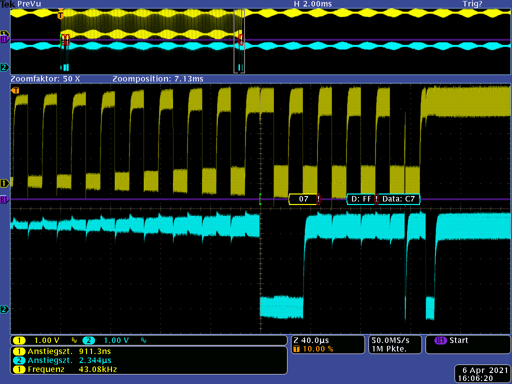
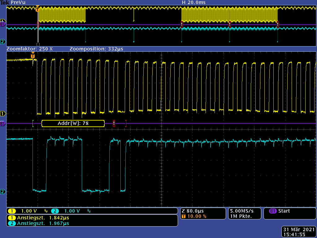
在 EMC 测试期间、我们注意到以下情况:

(参考所附 图像)

  • 传输在第一个1位被中止。 我们假设 USCI 此时检测到仲裁丢失错误、因为传入的射频会使信号失真。
  • 为什么 USCI 继续生成 CLK 时钟? 我们是否可以采取任何措施来防止这种情况?
  • 在第二次传输开始之前、USCI 被软件复位并重新初始化。 时钟一直运行、直到这个软件启动的复位。 为什么它一直运行到这里?
  • 根据系列用户指南、如果 USCI 检测到仲裁丢失错误、UCALIFG 将被置位。 当 UCALIFG 被置位时、UCMST 位被清零并且 I2C 控制器成为一个从器件。 但是在 UCMST 被清零后、USCI 不应该生成任何时钟!!!  (我们都在单主控模式下运行、从器件不会生成任何时钟!)

Oscillogram 1

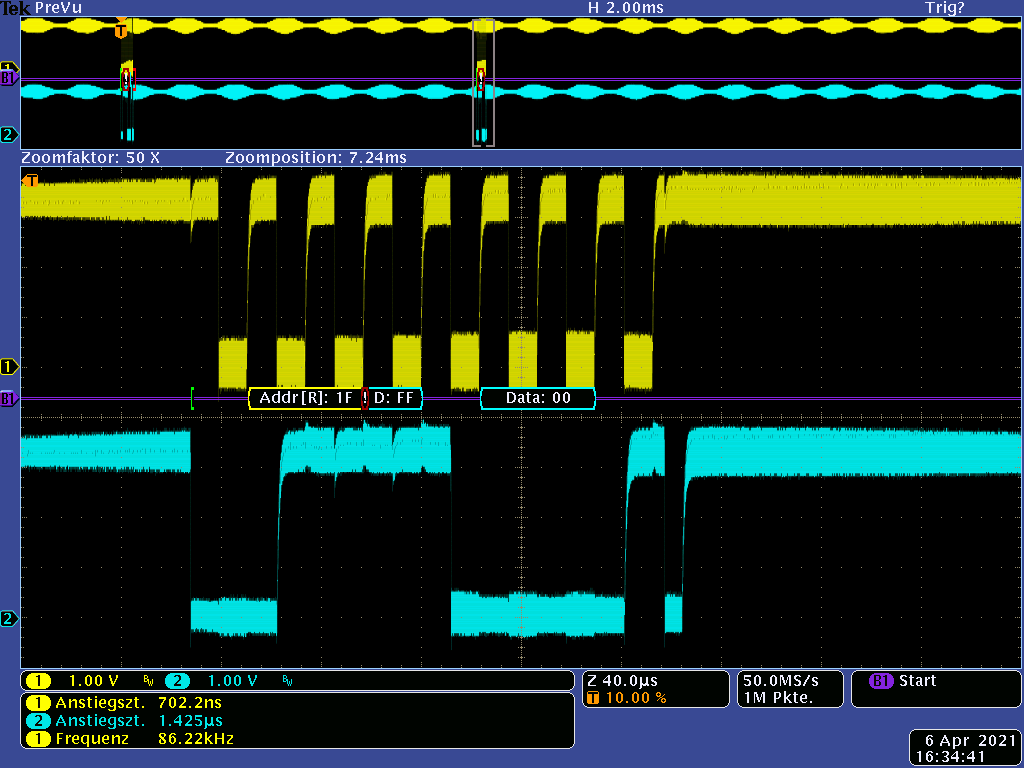
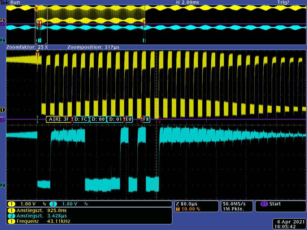
此外、我们还观察到(下一个图像)、即使射频暴露已结束、计时也会继续进行。

  • SDA 一直为高电平。 可以看到大约20个时钟。 这些必须来自 USCI!
  • 为什么 USCI 不会停止? 因为在8个时钟和一个 NACK 之后、USCI 应保持静止。
  • USCI 如何进入该状态?

Oscillogram 2

我们期待您的答复。

谢谢。

<<<<<<<<<<<<<<<<<<<<<<<<<<<<<<<<<<<<< 第一个帖子的结尾 >>>>>>>>>>>>

第3个帖子的附加内容:

  • 请注意,本文内容源自机器翻译,可能存在语法或其它翻译错误,仅供参考。如需获取准确内容,请参阅链接中的英语原文或自行翻译。

    尊敬的 Peter:

    您在 I2C mater 模式下使用 F2618、对吧? 您可以共享一些代码吗?

    谢谢!

    此致

    Johnson

  • 请注意,本文内容源自机器翻译,可能存在语法或其它翻译错误,仅供参考。如需获取准确内容,请参阅链接中的英语原文或自行翻译。

    尊敬的 Johnson:

    在我们的代码中、我们严格遵循 TI 应用报告 slaa382A 中使用 USCI I2C 主器 件的代码(从您的网站 www.ti.com/.../slaa382获取)。

    我们将 USCI 与 DMA 结合使用。

    因此、对传输的调用如下所示:


          if(!(*((*PtrRead).Ptr_BytesToSend) & 0x01)) // Tx
          {
            TI_USCI_I2C_DMA_transmitinit(set_address(), I2C_prescale);
            TI_USCI_I2C_DMA_transmit((*PtrRead).No_DataBytes,(*PtrRead).Ptr_BytesToSend+1);
          }
          else  // Rx
          {
            TI_USCI_I2C_DMA_receiveinit(set_address(), I2C_prescale);
            TI_USCI_I2C_DMA_receive((*PtrRead).No_DataBytes,(*PtrRead).Ptr_MemToStoreTo);
          }
    

    我们实际上使用应用报告中的 TI_USCI_I2C_MASTER_DMA.c 和.h、由 TI 的最佳编程器 Uli Kretzschmar 和 Christian Hernitschcheck 进行编码。

    这是否足够的代码示例?

  • 请注意,本文内容源自机器翻译,可能存在语法或其它翻译错误,仅供参考。如需获取准确内容,请参阅链接中的英语原文或自行翻译。

    您好、Johnson、
    我们继续研究这个问题。
    我们无法确认我们怀疑观察到的 USCI 不当行为与仲裁损失有关。

    为了排除软件中的错误、我们构建了一个简单的测试软件、该软件基本上包含应用报告 SLAA382中的原始代码示例。
    我们只在 main()中对一个小循环进行了编程,以使总线上持续有帧,并作出了检测仲裁丢失的规定。

    需要明确的是:我们只有(几乎)个原始的 TI 软件(带有 DMA)和在总线上没有从器件的 MSP430、并了解以下内容:

    请参阅第1个帖子中的第3个图像  (插入图像在回复模式下无法正常工作 )

    请按照以下有关图像的说明操作:
    -循环每隔~32ms 向 addr 0x78发送一个帧。
    由于不存在从器件,因此 addr 不会被应答。
    -StopCondition 也是正确的。
    但有时 USCI 会开始独立发送时钟、直到软件发送下一帧。

    是的、我们使用较小的 EMC 干扰辐射干扰 MSP。 但这样做不可能导致级别违规。 然而、它并未解释 USCI 毫无理由地永久发送时钟。
    如何防止这种情况???

    USCI 的这种行为存在一个大问题。
    因为如果在向外部存储器传输期间发生错误、我们观察到完整内容被0xFF 覆盖!

    下面是完整的代码:

    /*** USCI master library with DMA **********************************************
    
    In this file the usage of the USCI I2C master library with DMA support is shown. 
    This library uses pointers to specify what data is to be sent. The usage of the 
    DMA is transparent to the user.
    
    When calling the TI_USCI_I2C_DMA_receive or TI_USCI_I2C_DMA_transmit routines 
    the number of bytes, which are to be transmitted or received have to be passed  
    as well as a pointer to a data field, that contains(or stores) the data.
    
    This code checks if there is a slave with address 0x50 is connected to the I2C
    bus and if the slave device is present, bytes are received and transmitted.
    
    Uli Kretzschmar
    MSP430 Systems
    Freising
    *******************************************************************************/
    #include "msp430x26x.h"
    #include "TI_USCI_I2C_master_dma.h"
    
    typedef unsigned char  u8;
    typedef  unsigned int u16;
    
    __no_init volatile struct
                       {
                         u8 MOD:5;                  //!< DCO: Modulator selection
                         u8 DCO:3;                  //!< DCO: Frequency selection
                       }DCOCTL_Reg @ DCOCTL_;       //!< Bitfield zur Einstellung der DCO-Frequenz
    __no_init volatile struct
                       {
                         u8 RSEL   :4;              //!< DCO: Range Selection
                         u8 DIVA   :2;              //!< DCO: Divider for ACLK
                         u8 XTS_1  :1;              //!< DCO: LFXT1 mode select
                         u8 XT2_OFF:1;              //!< DCO: XT2 off
                       }BCSCTL1_Reg @ BCSCTL1_;     //!< Bitfield zur Einstellung der DCO-Frequenz
    
    #define RSEL_Value 11                           //!< DCO setzen [3,00MHz...5,50MHz], DCO_11_3
    #define DCO_Value  3                            //!< DCO setzen [3,00MHz...5,50MHz], DCO_11_3
    #define MOD_Value  15                           //!< DCO setzen [3,00MHz...5,50MHz], DCO_11_3
    const u16 I2C_prescale = 88;     //!< Teiler für die Taktrate bei I2C, 4,13 MHz / 88 = 46,9 kHz
    
    unsigned char array[40] = { 0x00, 0x02, 0x3, 0x4, 0x5, 0x6, 0x7, 0x8, 0x9, 0xa, 0xb };
    
    #define I2C_Slave_Adr_LCD 0x78 >> 1
    
    void main(void)
    {
      WDTCTL = WDTPW + WDTHOLD;                 // Stop WDT
    
      BCSCTL1_Reg.RSEL = RSEL_Value;     // DCO aus 4,13 MHz einstellen
      DCOCTL_Reg.DCO = DCO_Value;        // DCO aus 4,13 MHz einstellen
      DCOCTL_Reg.MOD = MOD_Value;        // DCO aus 4,13 MHz einstellen
    
      _EINT();
    
      TI_USCI_I2C_DMA_transmitinit(I2C_Slave_Adr_LCD,I2C_prescale);// init transmitting with USCI and DMA
      do
      {
        TI_USCI_I2C_DMA_transmitinit(I2C_Slave_Adr_LCD,I2C_prescale);// init transmitting with USCI and DMA
        TI_USCI_I2C_DMA_transmit(2,array);       // start transmitting with DMA
        
        for(u16 i=0; i < 10000; i++)        // waste time ~32ms
        {
          _NOP();
        }
      }
      while(1);
    }


    //******************************************************************************
    //   MSP430 USCI I2C Transmitter and Receiver with DMA support
    //
    //  Description: This code configures the MSP430's USCI module as 
    //  I2C master capable of transmitting and receiving bytes. DMA is used for
    //  transmitting and receiving of data.
    //
    //  ***THIS IS THE MASTER CODE***
    //
    //                    Master                   
    //                 MSP430F2619             
    //             -----------------          
    //         /|\|              XIN|-   
    //          | |                 |     
    //          --|RST          XOUT|-    
    //            |                 |        
    //            |                 |        
    //            |                 |       
    //            |         SDA/P3.1|------->
    //            |         SCL/P3.2|------->
    //
    // Note: External pull-ups are needed for SDA & SCL
    //
    // Uli Kretzschmar
    // Texas Instruments Deutschland GmbH
    // November 2007
    // Built with IAR Embedded Workbench Version: 3.42A
    //******************************************************************************
    #include "msp430x26x.h"                        // device specific header
    #include "TI_USCI_I2C_master_dma.h"
    
    unsigned char byteCtr;
    unsigned char last;
    unsigned char *save;
    
    //------------------------------------------------------------------------------
    // void TI_USCI_I2C_DMA_transmitinit(unsigned char slave_address, 
    //                                   unsigned char prescale)
    //
    // This function initializes the USCI module for master-transmit operation. 
    //
    // IN:   unsigned char slave_address   =>  Slave Address
    //       unsigned char prescale        =>  SCL clock adjustment 
    //------------------------------------------------------------------------------
    void TI_USCI_I2C_DMA_transmitinit( unsigned char slave_address, 
                                       unsigned char prescale)
    {
      // USCI module initialization
      P3SEL |= SDA_PIN + SCL_PIN;                 // Assign I2C pins to USCI_B0
      UCB0CTL1 = UCSWRST;                        // Enable SW reset
      UCB0CTL0 = UCMST + UCMODE_3 + UCSYNC;       // I2C Master, synchronous mode
      UCB0CTL1 = UCSSEL_2 + UCSWRST;              // Use SMCLK, keep SW reset
      UCB0BR0 = prescale;                         // set prescaler
      UCB0BR1 = 0;
      UCB0I2CSA = slave_address;                  // Set slave address
      UCB0I2CIE = UCNACKIE + UCALIE;
      UCB0CTL1 &= ~UCSWRST;                       // Clear SW reset,resume operation
    
      // DMA initialization
      DMA0CTL &= 0;                               // disable DMA channel 0
      DMACTL0 = DMA0TSEL_13;                      // select UCB0RXIFG is dma trigger
      DMA0CTL |= DMASRCINCR_3;                    // incremet source addr after dma
      DMA0CTL |= (DMADSTBYTE + DMASRCBYTE);       // byte to byte transfer
      DMA0CTL |= DMAIE;                           // enable dma interrupt
      DMA0DA = (unsigned short) &UCB0TXBUF;        // set DMA dest address register
    
    }
    
    //------------------------------------------------------------------------------
    // void TI_USCI_I2C_DMA_transmit(unsigned char byteCount, unsigned char *field)
    //
    // This function is used to start an I2C commuincation in master-transmit mode. 
    //
    // IN:   unsigned char byteCount  =>  number of bytes that should be transmitted
    //       unsigned char *field     =>  array variable. Its content will be sent.
    //------------------------------------------------------------------------------
    void TI_USCI_I2C_DMA_transmit(unsigned char byteCount, unsigned char *field){
      DMA0SA = (unsigned long) field;             // set DMA src address register  
      DMA0SZ = byteCount ;                    // block size 
      DMA0CTL |= DMAEN;                           // enable DMA channel 0  
      
      UCB0CTL1 |= UCTR + UCTXSTT;                 // I2C TX, start condition
    }
    
    #pragma vector = USCIAB0RX_VECTOR
    __interrupt void USCIAB0RX_ISR(void)
    {
      if (UCB0STAT & UCNACKIFG){            // send STOP if slave sends NACK
        UCB0CTL1 |= UCTXSTP;
        UCB0STAT &= ~UCNACKIFG;
      }
    
      if (UCB0STAT & UCALIFG){
        while(1);
      }
    }
    
    #pragma vector = USCIAB0TX_VECTOR
    __interrupt void USCIAB0TX_ISR(void)
    {
      if ((IFG2 & UCB0RXIFG) && (DMA0CTL & DMAIE))	// RX
      {
        if (last == 2)
        {
          UCB0CTL1 |= UCTXSTP;
          save[byteCtr-2] = UCB0RXBUF;
          last--;
        }
        else
        {
          save[byteCtr-1] = UCB0RXBUF;
          IFG2 &= ~UCB0RXIFG;
          IE2 &= UCB0RXIE;
        }
      }
      else											// TX immer mit DMA
      {
        UCB0CTL1 |= UCTXSTP;
        IFG2 &= ~UCB0TXIFG;
        IE2 &= UCB0TXIE;
      }
    
    }
    
    // DMA interrupt service routine
    #pragma vector=DMA_VECTOR
    __interrupt void dma (void)
    { 
      DMA0CTL &= ~DMAIFG;
      if (UCB0CTL1 & UCTR)            // wait til next TX-int to send stop condition
        IE2 |= UCB0TXIE;
      else 
      {
        IE2 |= UCB0RXIE;                      // enable RX int to receive last 
      }
    }


    /*** USCI master library with DMA **********************************************
    
    Uli Kretzschmar
    MSP430 Systems
    Freising
    *******************************************************************************/
    #ifndef USCI_LIB
    #define USCI_LIB
    
    #define SDA_PIN 0x02                                  // msp430x261x UCB0SDA pin
    #define SCL_PIN 0x04                                  // msp430x261x UCB0SCL pin
    
    void TI_USCI_I2C_DMA_transmitinit( unsigned char slave_address, 
                                   unsigned char prescale);
    
    void TI_USCI_I2C_DMA_transmit(unsigned char byteCount, unsigned char *field);
    
    #endif
    

    其他注意事项:我们尝试了应用报告中的代码示例-有和没有 DMA -并获得了相同的结果。

  • 请注意,本文内容源自机器翻译,可能存在语法或其它翻译错误,仅供参考。如需获取准确内容,请参阅链接中的英语原文或自行翻译。

    尊敬的 Peter:

    我使用 MSP430F2619在我的一侧进行了一些测试(与 F2618相同)、我没有发现任何 SCL 异常。

    附加我的测试代码:

    /* --COPYRIGHT--,BSD_EX
     * Copyright (c) 2012, Texas Instruments Incorporated
     * All rights reserved.
     *
     * Redistribution and use in source and binary forms, with or without
     * modification, are permitted provided that the following conditions
     * are met:
     *
     * *  Redistributions of source code must retain the above copyright
     *    notice, this list of conditions and the following disclaimer.
     *
     * *  Redistributions in binary form must reproduce the above copyright
     *    notice, this list of conditions and the following disclaimer in the
     *    documentation and/or other materials provided with the distribution.
     *
     * *  Neither the name of Texas Instruments Incorporated nor the names of
     *    its contributors may be used to endorse or promote products derived
     *    from this software without specific prior written permission.
     *
     * THIS SOFTWARE IS PROVIDED BY THE COPYRIGHT HOLDERS AND CONTRIBUTORS "AS IS"
     * AND ANY EXPRESS OR IMPLIED WARRANTIES, INCLUDING, BUT NOT LIMITED TO,
     * THE IMPLIED WARRANTIES OF MERCHANTABILITY AND FITNESS FOR A PARTICULAR
     * PURPOSE ARE DISCLAIMED. IN NO EVENT SHALL THE COPYRIGHT OWNER OR
     * CONTRIBUTORS BE LIABLE FOR ANY DIRECT, INDIRECT, INCIDENTAL, SPECIAL,
     * EXEMPLARY, OR CONSEQUENTIAL DAMAGES (INCLUDING, BUT NOT LIMITED TO,
     * PROCUREMENT OF SUBSTITUTE GOODS OR SERVICES; LOSS OF USE, DATA, OR PROFITS;
     * OR BUSINESS INTERRUPTION) HOWEVER CAUSED AND ON ANY THEORY OF LIABILITY,
     * WHETHER IN CONTRACT, STRICT LIABILITY, OR TORT (INCLUDING NEGLIGENCE OR
     * OTHERWISE) ARISING IN ANY WAY OUT OF THE USE OF THIS SOFTWARE,
     * EVEN IF ADVISED OF THE POSSIBILITY OF SUCH DAMAGE.
     *
     *******************************************************************************
     *
     *                       MSP430 CODE EXAMPLE DISCLAIMER
     *
     * MSP430 code examples are self-contained low-level programs that typically
     * demonstrate a single peripheral function or device feature in a highly
     * concise manner. For this the code may rely on the device's power-on default
     * register values and settings such as the clock configuration and care must
     * be taken when combining code from several examples to avoid potential side
     * effects. Also see www.ti.com/grace for a GUI- and www.ti.com/msp430ware
     * for an API functional library-approach to peripheral configuration.
     *
     * --/COPYRIGHT--*/
    //******************************************************************************
    //  MSP430F26x Demo - USCI_B0 I2C Master TX single bytes to MSP430 Slave
    //
    //  Description: This demo connects two MSP430's via the I2C bus. The master
    //  transmits to the slave. This is the master code. It continuously
    //  transmits 00h, 01h, ..., 0ffh and demonstrates how to implement an I2C
    //  master transmitter sending a single byte using the USCI_B0 TX interrupt.
    //  ACLK = n/a, MCLK = SMCLK = BRCLK = default DCO = ~1.045MHz
    //
    // ***to be used with "MSP430x261x_uscib0_i2c_07.c" ***
    //
    //                                /|\  /|\
    //               MSP430F261x/241x 10k  10k     MSP430F261x/241x
    //                   slave         |    |        master
    //             -----------------   |    |  -----------------
    //           -|XIN  P3.1/UCB0SDA|<-|---+->|P3.1/UCB0SDA  XIN|-
    //            |                 |  |      |                 |
    //           -|XOUT             |  |      |             XOUT|-
    //            |     P3.2/UCB0SCL|<-+----->|P3.2/UCB0SCL     |
    //            |                 |         |                 |
    //
    //  B. Nisarga
    //  Texas Instruments Inc.
    //  September 2007
    //  Built with CCE Version: 3.2.0 and IAR Embedded Workbench Version: 3.42A
    //******************************************************************************
    #include <msp430.h>
    
    unsigned char TXData;
    unsigned char TXByteCtr;
    
    int main(void)
    {
      WDTCTL = WDTPW + WDTHOLD;                 // Stop WDT
      P3SEL |= 0x06;                            // Assign I2C pins to USCI_B0
      UCB0CTL1 |= UCSWRST;                      // Enable SW reset
      UCB0CTL0 = UCMST + UCMODE_3 + UCSYNC;     // I2C Master, synchronous mode
      UCB0CTL1 = UCSSEL_2 + UCSWRST;            // Use SMCLK, keep SW reset
      UCB0BR0 = 12;                             // fSCL = SMCLK/12 = ~100kHz
      UCB0BR1 = 0;
      UCB0I2CSA = 0x48;                         // Slave Address is 048h
      UCB0CTL1 &= ~UCSWRST;                     // Clear SW reset, resume operation
      IE2 |= UCB0TXIE;                          // Enable TX interrupt
    
      TXData = 0x01;                            // Holds TX data
    
      while (1)
      {
        TXByteCtr = 1;                          // Load TX byte counter
        while (UCB0CTL1 & UCTXSTP);             // Ensure stop condition got sent
        UCB0CTL1 |= UCTR + UCTXSTT;             // I2C TX, start condition
        __bis_SR_register(CPUOFF + GIE);        // Enter LPM0 w/ interrupts
                                                // Remain in LPM0 until all data
                                                // is TX'd
        TXData++;                               // Increment data byte
      }
    }
    
    //------------------------------------------------------------------------------
    // The USCIAB0TX_ISR is structured such that it can be used to transmit any
    // number of bytes by pre-loading TXByteCtr with the byte count.
    //------------------------------------------------------------------------------
    #if defined(__TI_COMPILER_VERSION__) || defined(__IAR_SYSTEMS_ICC__)
    #pragma vector = USCIAB0TX_VECTOR
    __interrupt void USCIAB0TX_ISR(void)
    #elif defined(__GNUC__)
    void __attribute__ ((interrupt(USCIAB0TX_VECTOR))) USCIAB0TX_ISR (void)
    #else
    #error Compiler not supported!
    #endif
    {
      if (UCB0STAT & UCNACKIFG)
      {            // send STOP if slave sends NACK
          UCB0CTL1 |= UCTXSTP;
          UCB0STAT &= ~UCNACKIFG;
       }
      else if (TXByteCtr)                            // Check TX byte counter
      {
        UCB0TXBUF = TXData;                     // Load TX buffer
        TXByteCtr--;                            // Decrement TX byte counter
      }
      else
      {
        UCB0CTL1 |= UCTXSTP;                    // I2C stop condition
        IFG2 &= ~UCB0TXIFG;                     // Clear USCI_B0 TX int flag
        __bic_SR_register_on_exit(CPUOFF);      // Exit LPM0
      }
    }
    

    谢谢!

    此致

    Johnson

  • 请注意,本文内容源自机器翻译,可能存在语法或其它翻译错误,仅供参考。如需获取准确内容,请参阅链接中的英语原文或自行翻译。

    我在 G2553 (非 DMA)上看不到这种行为。 我将您的 main()与 SLAA382A 库一起使用。  

    我为 eUSCI 编写了一些代码、并清除了 UCNACKIFG 上的 DMAEN 和所有中断位(在这种情况下为 UCB0IE)(除了停止)。 如果您这么做、它会改变什么吗?

  • 请注意,本文内容源自机器翻译,可能存在语法或其它翻译错误,仅供参考。如需获取准确内容,请参阅链接中的英语原文或自行翻译。

    尊敬的 Johnson:

    我们已经尝试了您的代码。 但是、略有修改:

    • 将 DCO 加速至4、13MHz
    • 将 fSCL 设置为~46、9kHz
    • 将 USCIAB0RX_Vector 用于 NACK (您的代码不适用于 NACK。)
    • 帧之间的循环暂停时间约为7ms
    • 将从器件地址设置为0x78

    /* --COPYRIGHT--,BSD_EX
     * Copyright (c) 2012, Texas Instruments Incorporated
     * All rights reserved.
     *
     * Redistribution and use in source and binary forms, with or without
     * modification, are permitted provided that the following conditions
     * are met:
     *
     * *  Redistributions of source code must retain the above copyright
     *    notice, this list of conditions and the following disclaimer.
     *
     * *  Redistributions in binary form must reproduce the above copyright
     *    notice, this list of conditions and the following disclaimer in the
     *    documentation and/or other materials provided with the distribution.
     *
     * *  Neither the name of Texas Instruments Incorporated nor the names of
     *    its contributors may be used to endorse or promote products derived
     *    from this software without specific prior written permission.
     *
     * THIS SOFTWARE IS PROVIDED BY THE COPYRIGHT HOLDERS AND CONTRIBUTORS "AS IS"
     * AND ANY EXPRESS OR IMPLIED WARRANTIES, INCLUDING, BUT NOT LIMITED TO,
     * THE IMPLIED WARRANTIES OF MERCHANTABILITY AND FITNESS FOR A PARTICULAR
     * PURPOSE ARE DISCLAIMED. IN NO EVENT SHALL THE COPYRIGHT OWNER OR
     * CONTRIBUTORS BE LIABLE FOR ANY DIRECT, INDIRECT, INCIDENTAL, SPECIAL,
     * EXEMPLARY, OR CONSEQUENTIAL DAMAGES (INCLUDING, BUT NOT LIMITED TO,
     * PROCUREMENT OF SUBSTITUTE GOODS OR SERVICES; LOSS OF USE, DATA, OR PROFITS;
     * OR BUSINESS INTERRUPTION) HOWEVER CAUSED AND ON ANY THEORY OF LIABILITY,
     * WHETHER IN CONTRACT, STRICT LIABILITY, OR TORT (INCLUDING NEGLIGENCE OR
     * OTHERWISE) ARISING IN ANY WAY OUT OF THE USE OF THIS SOFTWARE,
     * EVEN IF ADVISED OF THE POSSIBILITY OF SUCH DAMAGE.
     *
     *******************************************************************************
     *
     *                       MSP430 CODE EXAMPLE DISCLAIMER
     *
     * MSP430 code examples are self-contained low-level programs that typically
     * demonstrate a single peripheral function or device feature in a highly
     * concise manner. For this the code may rely on the device's power-on default
     * register values and settings such as the clock configuration and care must
     * be taken when combining code from several examples to avoid potential side
     * effects. Also see www.ti.com/grace for a GUI- and www.ti.com/msp430ware
     * for an API functional library-approach to peripheral configuration.
     *
     * --/COPYRIGHT--*/
    //******************************************************************************
    //  MSP430F26x Demo - USCI_B0 I2C Master TX single bytes to MSP430 Slave
    //
    //  Description: This demo connects two MSP430's via the I2C bus. The master
    //  transmits to the slave. This is the master code. It continuously
    //  transmits 00h, 01h, ..., 0ffh and demonstrates how to implement an I2C
    //  master transmitter sending a single byte using the USCI_B0 TX interrupt.
    //  ACLK = n/a, MCLK = SMCLK = BRCLK = default DCO = ~1.045MHz
    //
    // ***to be used with "MSP430x261x_uscib0_i2c_07.c" ***
    //
    //                                /|\  /|\
    //               MSP430F261x/241x 10k  10k     MSP430F261x/241x
    //                   slave         |    |        master
    //             -----------------   |    |  -----------------
    //           -|XIN  P3.1/UCB0SDA|<-|---+->|P3.1/UCB0SDA  XIN|-
    //            |                 |  |      |                 |
    //           -|XOUT             |  |      |             XOUT|-
    //            |     P3.2/UCB0SCL|<-+----->|P3.2/UCB0SCL     |
    //            |                 |         |                 |
    //
    //  B. Nisarga
    //  Texas Instruments Inc.
    //  September 2007
    //  Built with CCE Version: 3.2.0 and IAR Embedded Workbench Version: 3.42A
    //******************************************************************************
    #include <msp430.h>
    
    unsigned char TXData;
    unsigned char TXByteCtr;
    
    int main(void)
    {
      WDTCTL = WDTPW + WDTHOLD;                 // Stop WDT
      
      // speed up DCO to 4,13 MHz
      BCSCTL1 &= ~(RSEL3 + RSEL2 + RSEL1+ RSEL0);
      BCSCTL1 |= RSEL3 + RSEL1+ RSEL0;      // RSEL = 11
      DCOCTL |= 0x6F;                       // DCO = 3, MOD = 15
    
      P3SEL |= 0x06;                            // Assign I2C pins to USCI_B0
      UCB0CTL1 |= UCSWRST;                      // Enable SW reset
      UCB0CTL0 = UCMST + UCMODE_3 + UCSYNC;     // I2C Master, synchronous mode
      UCB0CTL1 = UCSSEL_2 + UCSWRST;            // Use SMCLK, keep SW reset
      UCB0BR0 = 88;                             // fSCL = SMCLK/12 = ~100kHz @ SMCLK = 1 MHz
      UCB0BR1 = 0;                              // fSCL = 4,13 MHz / 88 = ~46,9 kHz
      UCB0I2CSA = 0x78 >> 1;                    // Slave Address is 0x78
      UCB0I2CIE = UCNACKIE;
      UCB0CTL1 &= ~UCSWRST;                     // Clear SW reset, resume operation
      IE2 |= UCB0TXIE;                          // Enable TX interrupt
    
      TXData = 0x01;                            // Holds TX data
    
      while (1)
      {
        TXByteCtr = 1;                          // Load TX byte counter
        while (UCB0CTL1 & UCTXSTP);             // Ensure stop condition got sent
        UCB0CTL1 |= UCTR + UCTXSTT;             // I2C TX, start condition
        __bis_SR_register(CPUOFF + GIE);        // Enter LPM0 w/ interrupts
                                                // Remain in LPM0 until all data
                                                // is TX'd
        TXData++;                               // Increment data byte
    
        for(unsigned int i=0; i < 3333; i++)        // waste time ~10ms
        {
          _NOP();
        }
      }
    }
    
    #pragma vector = USCIAB0RX_VECTOR
    __interrupt void USCIAB0RX_ISR(void)
    {
      if (UCB0STAT & UCNACKIFG){            // send STOP if slave sends NACK
        UCB0CTL1 |= UCTXSTP;
        UCB0STAT &= ~UCNACKIFG;
        __bic_SR_register_on_exit(CPUOFF);      // Exit LPM0
      }
    }
    
    //------------------------------------------------------------------------------
    // The USCIAB0TX_ISR is structured such that it can be used to transmit any
    // number of bytes by pre-loading TXByteCtr with the byte count.
    //------------------------------------------------------------------------------
    #if defined(__TI_COMPILER_VERSION__) || defined(__IAR_SYSTEMS_ICC__)
    #pragma vector = USCIAB0TX_VECTOR
    __interrupt void USCIAB0TX_ISR(void)
    #elif defined(__GNUC__)
    void __attribute__ ((interrupt(USCIAB0TX_VECTOR))) USCIAB0TX_ISR (void)
    #else
    #error Compiler not supported!
    #endif
    {
      if(TXByteCtr)                             // Check TX byte counter
      {
        UCB0TXBUF = TXData;                     // Load TX buffer (and clear UCB0TXIFG !!!)
        TXByteCtr--;                            // Decrement TX byte counter
      }
      else
      {
        UCB0CTL1 |= UCTXSTP;                    // I2C stop condition
        IFG2 &= ~UCB0TXIFG;                     // Clear USCI_B0 TX int flag
        __bic_SR_register_on_exit(CPUOFF);      // Exit LPM0
      }
    }

    我们的观察结果如下:

    1. 设置:发送一个字节到从器件0x78、以中等 EMC 干扰辐射干扰 MSP
      此图显示了 USCI 的良好行为。


    2. 设置:向从机0x78发送一个字节。 在这里、MSP 暴露于满足标准要求的辐射中。

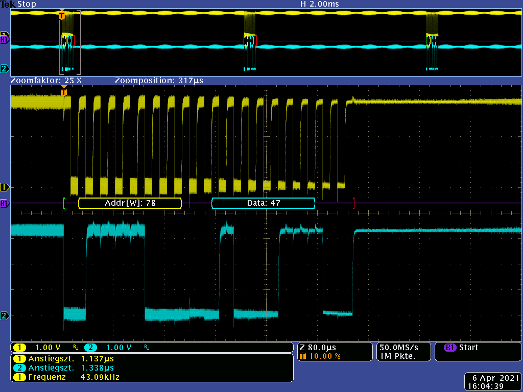
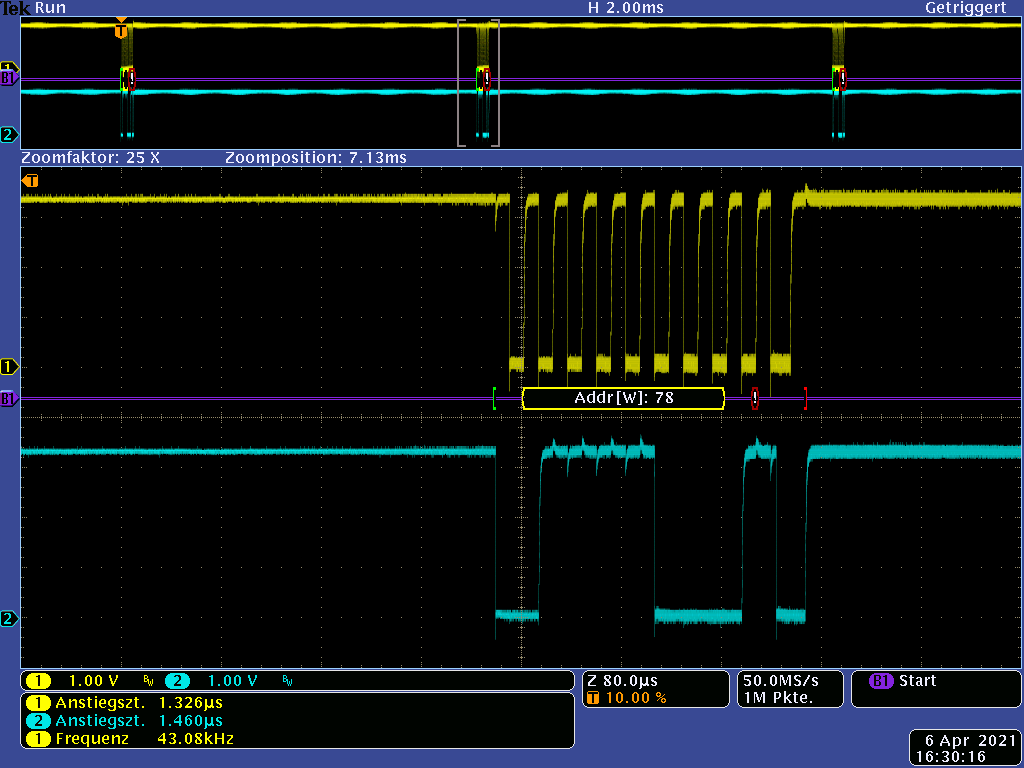
       -使用 ACK 寻址0x78看起来是正确的。
      数据字节看起来像10101111
      但从这里看,USCI 做的事情是无法解释的。 SCL 开始运行、运行和运行;直到下一帧开始。 USCI 中会发生什么情况?

    3. 设置为2。 相同的照射行程、缩放区域移~7ms 至下一帧

      -SCL 自前一帧起一直运行。
      ——前半部分的地址看起来不错。
      从第五个时钟开始出现问题...
      - SDA 的最后一个上升沿可能是一个停止条件的尝试。
      -从这里开始、软件站在危险 while (UCB0CTL1 & UCTXSTP);循环(第101行)。 7ms 后的帧不再出现。

    4. SETUP:主器件寻址从器件、但从器件不响应/不存在。 MSP 暴露在低 EMC 干扰辐射下。


      这看起来不错。

    5. 设置与4相同。 但 MSP 暴露于符合标准要求的辐射中。


      在第八个时钟发生了问题。
      USCI 给出的地址完全错误。 地址0x78的前四位是正确的。 之后出现错误位!
      -在这里、软件也站在危险的 while (UCB0CTL1 & UCTXSTP);循环(第101行)。 7ms 后的帧不再出现。

    再说一次、是的、我们会使 MSP 受到辐射干扰。 但是、对于在示波器记录中可以看到的 USCI 的错误行为、既没有解释也没有显示工作范围。

    因此我们迫切需要帮助! 请将此支持请求转发给弗莱辛的二级支持。

    谢谢你。

    此致、

    Peter

  • 请注意,本文内容源自机器翻译,可能存在语法或其它翻译错误,仅供参考。如需获取准确内容,请参阅链接中的英语原文或自行翻译。

    尊敬的 Peter:

    让我们通过电子邮件沟通、帮助您快速解决问题。

    谢谢!

    此致

    Johnson