大家好、我 正在 开发红外发射器。
目前、我正在尝试将 MSP430FR4133板与给定的 TI 库结合使用。
我有两个问题;
代码如下所示、
unsigned char send_data[8]={0xFF、0xFF、0xFF、0xFF、0x10、0xEF、0xEB、0x14};发送此数据但接收 未知数据。
请听听我的解决方案。
2.此代码需要任何库或驱动程序?
This thread has been locked.
If you have a related question, please click the "Ask a related question" button in the top right corner. The newly created question will be automatically linked to this question.
大家好、我 正在 开发红外发射器。
目前、我正在尝试将 MSP430FR4133板与给定的 TI 库结合使用。
我有两个问题;
代码如下所示、
unsigned char send_data[8]={0xFF、0xFF、0xFF、0xFF、0x10、0xEF、0xEB、0x14};发送此数据但接收 未知数据。
请听听我的解决方案。
2.此代码需要任何库或驱动程序?
#include "msp430.h" unsigned char IR_code; unsigned char IR_flag; unsigned char IR_stop; unsigned char byte_cnt; unsigned int bit_sel; unsigned char *send_addr; unsigned char send_data[8]={0xFF,0xFF,0xFF,0xFF,0x10,0xEF,0xEB,0x14}; // Unsigned data will displayed { // Watchdog timer works as default setting WDTCTL = WDTPW + WDTHOLD; Init_GPIO(); Init_Clock(); IR_stop = 1; //disable IR emitter while(1) { // clear the flag and counter IR_flag = 0; byte_cnt = 0; bit_sel = 0; if(IR_stop == 0) { // Configure IR output pin P1SEL0|= BIT0; // use internal IR modulator // disable Port1 & Port2 interrupt during IR emitting P1IE = 0; P2IE = 0; // IR_code = scan_key(); // scan the keypad // Configure IR modulation: ASK SYSCFG1 = IRDSSEL + IREN; TA1CCTL0 = CCIE; TA1CCTL2 = OUTMOD_7; // output mode: reset/set TA0CCTL2 = OUTMOD_7; // output mode: reset/set // 38kHz 1/4 duty-cycle carrier waveform length setting TA0CCR0 = 104; TA0CCR2 = 25; TA1CCR0 = 640; //the initial time of TA0 should be longer than TA1 TA1CCR2 = 320; // set timer operation mode TA0CTL = TASSEL_2 + MC_1 + TACLR; //SMCLK, UP mode TA1CTL = TASSEL_2 + MC_1 + TACLR; //SMCLK, UP mode // write button number into buffer //send_data[2] = IR_code; //send_data[3] = ~IR_code; send_addr = &send_data[0]; /*while (1) { if (buttonPressed) { buttonPressed = 0; if (!irDataValid) { // start IR transmission transmitCode(send_data); } }*/ // stop until the end of IR code while(IR_stop == 0); TA0CCTL0 = 0; TA0CCTL2 = 0; TA0CTL = 0; TA0CCR0 = 0; TA0CCR2 = 0; //disable timer0 TA1CCTL0 = 0; TA1CCTL2 = 0; TA1CTL = 0; TA1CCR0 = 0; TA1CCR2 = 0; //disable timer1 P1IE |= (BIT3 + BIT4 + BIT5); //enable GPIO interrupt P2IE |= BIT7; } // __bis_SR_register(LPM3_bits | GIE); //enter low power mode IR_stop = 0; // enable IR code emitting } } //********Timer1 interrupt ISR*********// #pragma vector = TIMER1_A0_VECTOR __interrupt void TIMER1_A0_ISR (void) { switch( TA1IV ) { case 0: { if(IR_flag) { IR_stop=1; // stop IR modulator TA1CCTL0 &= ~CCIE; // disable timer_A0 interrupt } if((byte_cnt==0)&& (bit_sel==0)) // leading pulse burst of IR code { TA1CCR0 = 53999; // 9ms high TA1CCR2 = 35999; // 4.5ms low byte_cnt++; // byte counter bit_sel++; // bit counter } else if((byte_cnt>= 5)&& (bit_sel==1)) // the end of IR code { TA1CCR0 = 2249; //0.562ms pulse burst to show the end TA1CCR2 = 2249; IR_flag=1; } else { if((*send_addr & bit_sel) == 0) // data "0" { TA1CCR0 = 4499; // 0.562ms high 0.562ms low TA1CCR2 = 2249; bit_sel<<=1; } else // data "1" { TA1CCR0 = 8999; // 0.562ms high 1.687ms low TA1CCR2 = 2249; bit_sel<<=1; } if(bit_sel>=256) // start a new byte { send_addr++; byte_cnt++; bit_sel=1; } } break; } default: break; } }
您好、Trupti、
[引用 userid="553020" url="~/support/microcontrollers/msp-low-power-microcontrollers-group/msp430/f/msp-low-power-microcontroller-forum/1197569/infrared-emitting-data-and-receiving-unknown-data "]代码如下所示、
unsigned char send_data[8]={0xFF、0xFF、0xFF、0xFF、0x10、0xEF、0xEB、0x14};发送此数据但接收 未知数据。
[/报价]您如何验证您是否看到未知数据? 您是否在接收器中观察 RX_Data 缓冲器? 您是否正在使用另一个带有 BOOST-IR Booster Pack 的 launchpad 作为接收器或其他器件? MSP430FR4133和 BOOST-IR BoosterPack 的接收器示例代码通常仅接收4个字节。
[引用 userid="553020" url="~/support/microcontrollers/msp-low-power-microcontrollers-group/msp430/f/msp-low-power-microcontroller-forum/1197569/infrared-emitting-data-and-receiving-unknown-data "]2.此代码需要任何库或驱动程序?
[/报价]
查看这一点、您需要使用项目中包含的 HAL 文件中的代码。 以及 MSP430.h 中包含的寄存器定义
我认为这里没有任何其他要求、但如果这里有缺失或未定义的符号、则在编译时会生成错误。
此致、
Brandon Fisher
我使用 Arduino 作为接收器、它是否可以接收 RX_DATA?
您好、Trupti、
我无法说出您正在使用的 Arduino 是什么、但如果一切都正确、则应该可以接收 RX 数据。
您在 Arduino 端使用哪种接收器? 您确定载波频率相同吗?
此致、
Brandon Fisher
您好 、Brandon Fisher、
我正在使用 TSOP13238 38kHz AGC2 接收器。
在代码下方、只需禁用"键盘"部分。
#include "msp430.h"
#include "HAL_FR4133LP_LCD.h"//声明并包含在 seprate 文件中
#include "HAL_FR4133LP_Board.h"//声明并包含在 seprate 文件中
unsigned char IR_code;
unsigned char IR_FLAG;
unsigned char IR_stop;
unsigned char byte_cnt;
unsigned int bit_SEL;
unsigned char * send_addr;
//unsigned char send_data[4]={0x55、0xAA、0x00、0xff};//将显示 unsigned data
将显示 unsigned char send_data[4]={0x10、0xEF、0xEB、0x14};// unsigned data
int main( void )
{
//看门狗计时器作为默认设置工作
WDTCTL = WDTPW + WDTHOLD;
init_gpio();//初始化 GPIO
init_Clock();//Initialize Clock
//Init_keypadio();//初始化键盘
init_lcd();//初始化 LCD
LCD_Display_MSP_IR ();//显示"MSP--IR"
LCD_Display_TX ();//显示"TX"
IR_STOP = 1;//禁用 IR 发射器
while (1)
{
//清除标志和计数器
IR_FLAG = 0;
byte_cnt = 0;
bit_SEL = 0;
if (IR_STOP = 0)
{
//配置 IR 输出引脚
P1SEL0|= BIT0;//使用内部红外调制器
//在发出 IR 时禁用 Port1和 Port2中断
P1IE = 0;
P2IE = 0;
// IR_code = scan_key();//扫描键盘
//配置红外调制:询问
SYSCFG1 = IRDSSEL + IREN;
TA1CCTL0 = CCIE;
TA1CCTL2 = OUTMOD_7;//输出模式:复位/置位
TA0CCTL2 = OUTMOD_7;//输出模式:复位/置位
// 38kHz 1/4占空比载波长度设置
TA0CCR0 = 104;
TA0CCR2 = 25;
TA1CCR0 = 640;// TA0的初始时间应长于 TA1
TA1CCR2 = 320;
//设置计时器操作模式
TA0CTL = tassel_2 + MC_1 + TACLR;//SMCLK、向上计数模式
TA1CTL = tassel_2 + MC_1 + TACLR;//SMCLK、向上计数模式
//将按钮编号写入缓冲区
//send_data[2]= IR_code;
//send_data[3]=~IR_code;
send_addr =&send_data[0];
//停止,直到 IR 代码结束
while (IR_STOP = 0);
TA0CCTL0 = 0;
TA0CCTL2 = 0;
TA0CTL = 0;
TA0CCR0 = 0;
TA0CCR2 = 0;//禁用 timer0
TA1CCTL0 = 0;
TA1CCTL2 = 0;
TA1CTL = 0;
TA1CCR0 = 0;
TA1CCR2 = 0;//禁用 Timer1
P1IE |=(BIT3 + BIT4 + BIT5);//启用 GPIO 中断
P2IE |= BIT7;
}
//_ bis_SR_register (LPM3_bits | GIE);//进入低功耗模式
IR_STOP = 0;//启用红外代码发光
}
}
//***** Timer1中断 ISR ******* //
#pragma vector = Timer1_A0_vector
_interrupt void Timer1_A0_ISR (void)
{
switch (TA1IV)
{
情况0:
{
if (IR_FLAG)
{
IR_STOP=1;//停止红外调制器
TA1CCTL0 &=~CCIE;//禁用 TIMER_A0中断
}
if ((byte_cnt=0)&&(bit_SEL=0)// IR 代码的前导脉冲突发
{
TA1CCR0 = 53999;// 9ms 高电平
TA1CCR2 = 35999;// 4.5ms 低电平
byte_cnt++;//字节计数器
bit_SEL++;//位计数器
}
否则、如果((byte_cnt>=5)&&(bit_SEL=1))// IR 代码结束
{
TA1CCR0 = 2249;//0.562ms 脉冲突发以显示结束
TA1CCR2 = 2249;
IR_FLAG=1;
}
其他
{
if ((* send_addr & bit_SEL)=0)//数据"0"
{
TA1CCR0 = 4499;// 0.562ms 高0.562ms 低
TA1CCR2 = 2249;
bit_SEL<<=1;
}
else //数据"1"
{
TA1CCR0 = 8999;// 0.562ms 高1.687ms 低
TA1CCR2 = 2249;
bit_SEL<<=1;
}
if (bit_SEL>=256)//开始一个新字节
{
SEND_ADDR++;
byte_cnt++;
bit_SEL=1;
}
}
中断;
}
默认值:break;
}
}
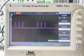
我正在检查端口 P1.0上的输出、输出脉冲低于图像。 这是正确的吗?
如何 确保载波频率相同?
"IR 远程"包括多种协议、大多数协议不可互操作。 我不记得 BOOST-IR 固件使用哪一个。
Arduino 库可以推断和解码许多/大多数常见协议。 这是一个2分钟内通过 Google 启动的项目:
https://learn.sparkfun.com/tutorials/ir-communication/all
似乎、即使该库无法确定它是什么协议、它也会为您提供接收到的代码、以便您可以在代码中检测它们。
这是输出正确吗?
我正在检查端口 P1.0上的输出、输出脉冲。
38kHz (载波)信号的周期约为26us、因此这些脉冲看起来很好。 更有趣的是这些脉冲的更高级别模式(缩小范围)。
更一般而言、我认为您使用38kHz (TSOP)接收器器件时没有遇到问题、因为您的应用报告的是"未知代码"、而不是[完全没有]。 您的应用是否对收到的内容有其他看法?
10分钟内使用 Google 建议 BOOST-IR 示例固件使用"NEC IR"协议(562us 脉冲、关闭时间为562us (0)或关闭时间为1.7us (1)、但有更多选择):
https://techdocs.altium.com/display/FPGA/NEC+Infrared+Transmission+Protocol
您的库是否知道此协议?
[编辑:少量澄清]