This thread has been locked.
If you have a related question, please click the "Ask a related question" button in the top right corner. The newly created question will be automatically linked to this question.
https://e2e.ti.com/support/power-management-group/power-management/f/power-management-forum/1548983/tps51215a-schematic-check
工具/软件:
你(们)好
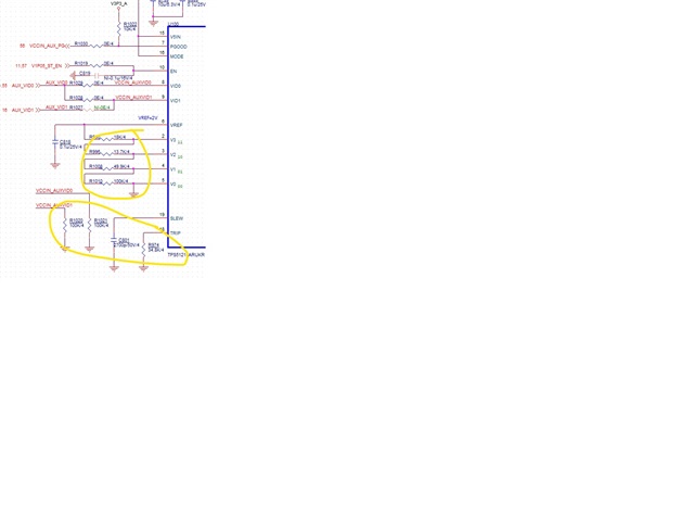
您能帮助查看下面的 TPS51215A 原理图以及任何需要进行调整吗
电感器为 0.22uH、DCR 为 0.63m Ω、替换为 0.22uH、DCR 为 0.29m Ω。
电感器 DRC 是不同的。 是否需要对电路上的黄色圆圈中的电阻进行微调?
谢谢
Gareth OU
您插入到帖子中的图形没有足够高的分辨率、无法对原理图审阅进行读取。
如果他们具有使用 220nH 0.62mΩ 电感器的有效设计、并替换为 220nH 0.29mΩ 电感器、则电感器 DCR 的变化不需要更改设计。
如果您需要更多审查、我们将需要查看分辨率更高的原理图图像。