This thread has been locked.

If you have a related question, please click the "Ask a related question" button in the top right corner. The newly created question will be automatically linked to this question.

[参考译文] UCC2897A:使用芯片 VIN 引脚上的电阻分压器电路将 UCC2897A 芯片应用于120V 输入。

Guru**** 2387080 points
Other Parts Discussed in Thread: UCC2897A
请注意,本文内容源自机器翻译,可能存在语法或其它翻译错误,仅供参考。如需获取准确内容,请参阅链接中的英语原文或自行翻译。

https://e2e.ti.com/support/power-management-group/power-management/f/power-management-forum/879589/ucc2897a-application-of-ucc2897a-chip-for-120v-input-using-resistor-divider-circuit-at-vin-pin-of-the-chip

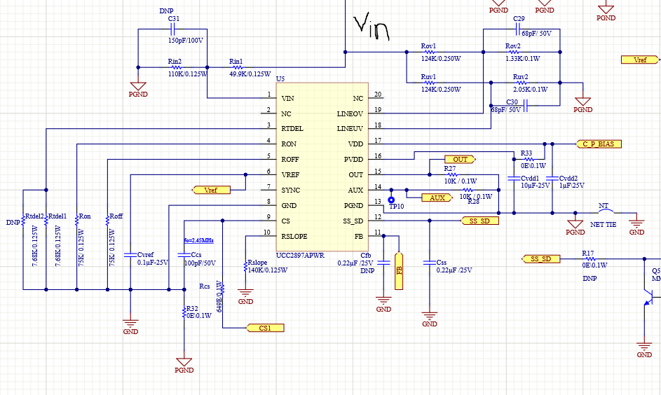
器件型号:UCC2897A

我尝试使用 UCC2897A 芯片实现120V 输入、在芯片的 VIN 引脚处使用电阻分压器电路、如原理图所示。 实际使用的 Rin1和 Rin2值均为25k Ω。 使用应用手册"了解和设计使用 UCC2897A 的有源钳位电流模式控制转换器"中提供的串联稳压器电路、VDD 引脚上的电压为11V。 现在的问题是、如果提供60V 输入电压、则 VDD 上的电压为11.57V、并且不会超过12.7V、这是启动芯片所必需的。 而 RIN2引脚上的电压也为11.57V、因此 RIN2上的电压为48.43V。 因此、流经 Rin1的电流将约为1.9mA。 该电流流向何处? 为什么不对 VDD 电容器充电?  


  • 请注意,本文内容源自机器翻译,可能存在语法或其它翻译错误,仅供参考。如需获取准确内容,请参阅链接中的英语原文或自行翻译。

    VIN 上的输入阻抗过高、UCC2897A 无法启动。

    我建议您在输入电压上使用下面显示的低阻抗稳压器。

    当 R7 = 20k 时,Vin 在启动时将能够提供高达3mA 的电源电流。

    此致

    John

  • 请注意,本文内容源自机器翻译,可能存在语法或其它翻译错误,仅供参考。如需获取准确内容,请参阅链接中的英语原文或自行翻译。

    谢谢 、John!  

    我认为这会有所帮助。