This thread has been locked.
If you have a related question, please click the "Ask a related question" button in the top right corner. The newly created question will be automatically linked to this question.
https://e2e.ti.com/support/power-management-group/power-management/f/power-management-forum/1316524/lm5143-q1-how-to-measure-bode-plot
尊敬的 TI
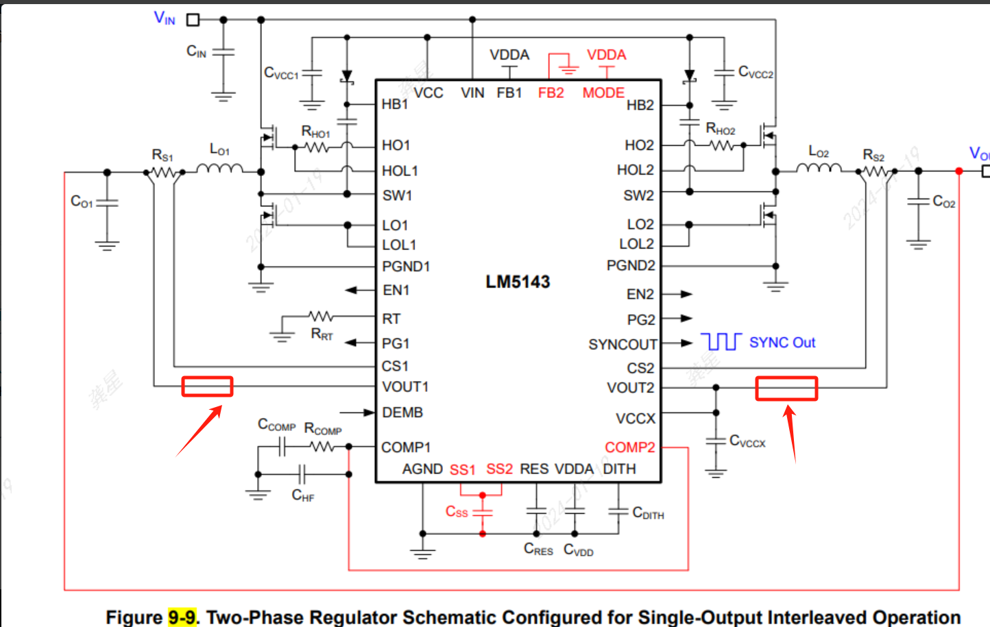
将 MODE 引脚连接 到 VDDA 以实现交错式信号输出操作、
在 信号输出运行时、如何 测量波特图?
将串联电阻器放置在何处?
谢谢!
您好!
您需要在 FB1引脚上放置一个电阻分压器、并在 RFBT 和 Vout 之间插入纹波注入电阻。
此致、
鸿嘉
你好,hong jia
因此、我们应该将 FB1连接到 Redriver、将 FB2连接到 AGND、 如果没有 Redriver、我们无法 测量波特图?
是的、正确。 环路测量需要使用电阻分压器。