

Other Parts Discussed in Thread: UCD3138A64
请注意,本文内容源自机器翻译,可能存在语法或其它翻译错误,仅供参考。如需获取准确内容,请参阅链接中的英语原文或自行翻译。
器件型号:UCD3138A64 大家好!
我正在尝试使用 UCD3138A64芯片实现 PSFB。 目前、我们需要仅在开环模式下运行设置、并使用外部连接的 POT 或使用 UCD GUI 手动更改相移。
我还使用代码添加了死区时间、但无法获得正确的输出。 UCD 的输出似乎存在倾斜(前缘和后缘的零周期不同)。
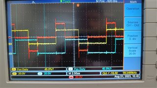
黄色和蓝色波形分别是 DPWM0A 和 DPWM1A 的输出。 给出了一定的相移以获得大约40%的相移。 但正如红色波形(DPWM0A - DPWM1A)中所示、它是不对称的。
如果我使用50%相移(我在 DPWMPHASE TRIG 寄存器中输入了事件2值)、则输出似乎没有问题。 我将在下面附加我的代码片段。
//###########################################################################
//
// FILE:  main.c
//
// TITLE: main
//
// NOTES:
//  1)

//###########################################################################
//
//  Ver  | dd mmm yyyy | Who  | Description of changes
// ======|=============|======|==============================================
//  1.00 | 05 May 2015 | CH  |
//
//  Texas Instruments, Inc
//  Copyright Texas Instruments 2008. All rights reserved.
//###########################################################################
//Changing phase shift by hyperknob
#define MAIN 1

#include "system_defines.h"
#include "Cyclone_Device.h"
#include "pmbus_commands.h"
#include "pmbus_common.h"
#include "pmbus_topology.h"
#include "variables.h"
#include "functions.h"
#include "software_interrupts.h"
#include "cyclone_defines.h"
#include "stdio.h"

#define PCLK_PERIOD 4.0e-9
#define PERIOD_SECONDS 10.0e-6
#define PERIOD ((int)(PERIOD_SECONDS/PCLK_PERIOD)<<4)
#define EVENT1 (int)(PERIOD*0.00+1000) //+2000 is deadtime added to the signal
#define EVENT2 (int)(PERIOD*0.50-1000)
#define EVENT3 (int)(PERIOD*0.50+1000) //+2000 is deadtime added to the signal
#define EVENT4 (int)(PERIOD*1.00-1000)

int temp;
//int ram_event2; // comment for hyperknob [min=0, max=20000, step=1800]
//step 1800=0.45us i.e. +1800 => 10% phase shift for 4.5us on time and 5.5us off time
void init_dpwm0(void)
{
    Dpwm0Regs.DPWMCTRL0.bit.PWM_EN = 0;     // disable DPWM0 locally during initilization

Dpwm0Regs.DPWMCTRL0.bit.CLA_EN = 0; // default is 1 (i.e. default is to use the filter output to control DPWM)

Dpwm0Regs.DPWMCTRL0.bit.PWM_A_INV = 0;
Dpwm0Regs.DPWMCTRL0.bit.PWM_B_INV = 0;

Dpwm0Regs.DPWMPRD.all = PERIOD;         // use .all for all values, so that the scaling matches
Dpwm0Regs.DPWMEV1.all = EVENT1;         // set EVENT 1 to 0% (start) of period
Dpwm0Regs.DPWMEV2.all = EVENT2;         // set EVENT 2 to 50% (start) of period
Dpwm0Regs.DPWMEV3.all = EVENT3;         // set EVENT 3 to 50% (start) of period
Dpwm0Regs.DPWMEV4.all = EVENT4;         // set EVENT 4 to 100% (start) of period

//----------------------------------------------------------------------------------
// lab 2 tasks:
// add initialization of DPWM events 2 through 4.
// - set EVENT 2 to 25% of period
// - set EVENT 3 to 50% of period
// - set EVENT 4 to 75% of period
 Dpwm1Regs.DPWMCTRL0.bit.PWM_EN = 0;     // disable DPWM0 locally during initilization

 Dpwm1Regs.DPWMCTRL0.bit.CLA_EN = 0; // default is 1 (i.e. default is to use the filter output to control DPWM)

 Dpwm1Regs.DPWMCTRL0.bit.PWM_A_INV = 0;
 Dpwm1Regs.DPWMCTRL0.bit.PWM_B_INV = 0;

 Dpwm1Regs.DPWMPRD.all = PERIOD;         // use .all for all values, so that the scaling matches
 Dpwm1Regs.DPWMEV1.all = EVENT1;         // set EVENT 1 to 0% (start) of period
 Dpwm1Regs.DPWMEV2.all = EVENT2;         // set EVENT 1 to 0% (start) of period
 Dpwm1Regs.DPWMEV3.all = EVENT3;         // set EVENT 1 to 0% (start) of period
 Dpwm1Regs.DPWMEV4.all = EVENT4;         // set EVENT 1 to 0% (start) of period

 Dpwm0Regs.DPWMPHASETRIG.all = EVENT2*0.5; //Phase shift

 LoopMuxRegs.DPWMMUX.bit.DPWM1_SYNC_SEL = 0;
 Dpwm1Regs.DPWMCTRL0.bit.MSYNC_SLAVE_EN = 1;


//----------------------------------------------------------------------------------

    Dpwm0Regs.DPWMCTRL0.bit.PWM_EN = 1;     // enable DPWM0 locally
LoopMuxRegs.GLBEN.bit.DPWM0_EN = 1;     // enable DPWM0 globally

Dpwm1Regs.DPWMCTRL0.bit.PWM_EN = 1;     // enable DPWM0 locally
LoopMuxRegs.GLBEN.bit.DPWM1_EN = 1;     // enable DPWM0 globally


}


void main()
{
// enable JTAG
MiscAnalogRegs.IOMUX.all = 0;

//---------------------------------------------------------------------------
// IMPORTANT: READ BELOW, OR CODE MAY NOT EXECUTE CORRECTLY
//---------------------------------------------------------------------------
// tie pin FAULT3 to ground for normal operation
// tie pin FAULT3 to 3.3V to clear checksum
if(GioRegs.FAULTIN.bit.FLT3_IN == 1)
{
clear_integrity_word();
}

#if (UCD3138|UCD3138064)
MiscAnalogRegs.CLKTRIM.bit.HFO_LN_FILTER_EN = 0;
MiscAnalogRegs.CSTRIM.bit.RESISTOR_TRIM =23; //28;
#endif

init_pmbus(0x58); // initialize PMBus handler
init_dpwm0(); // initialize DPWM0
//ram_event2 = Dpwm0Regs.DPWMPHASETRIG.all ; // initialize hyperknob
for(;;)
{
pmbus_handler();
//Dpwm0Regs.DPWMPHASETRIG.all = ram_event2; // put hyperknob value into register
}
}


void c_int00(void)
{
main();
}
如果需要如何操作才能获得正确的输出、请提供相关指南。
谢谢你。
