请注意,本文内容源自机器翻译,可能存在语法或其它翻译错误,仅供参考。如需获取准确内容,请参阅链接中的英语原文或自行翻译。
器件型号:LP5810 工具与软件:
您好!
我想使用一个连接到 I2C 的 LP5810A...D、 我使用广播地址。
我在连接到 Arduino Pro Micro 的 Arduino 中使用以下初始化代码:
无 PWM (0xFF)、调整 DC_Current
#define LP8510_Broadcast 0x1B
#define LP8510A 0x14
#define LP8510B 0x15
#define LP8510C 0x16
#define LP8510D 0x17
uint8_t LP8510_write(uint8_t chip_address, uint16_t register_address,uint8_t data)
{
uint8_t chip_address_dummy=0, register_address_dummy_8=0;
uint16_t register_address_dummy_16=0;
chip_address=chip_address << 2;
chip_address=chip_address&0x7F;
register_address_dummy_16=register_address&0x3FF;
register_address_dummy_8=register_address_dummy_16 >> 8;
chip_address_dummy=chip_address+register_address_dummy_8;
register_address_dummy_8=register_address&0xFF;
Wire.beginTransmission(chip_address_dummy);
Wire.write(register_address_dummy_8);
Wire.write(data);
return(Wire.endTransmission(true));
}
uint8_t LP8510_init(uint8_t chip_address)
{
uint8_t error=0;
error+=LP8510_write(chip_address, 0x000, 0x01);//Enable the internal circuits; 0h = Disable; 1h = Enable
error+=LP8510_write(chip_address, 0x023, 0x66);//Software reset; Write 66h to reset
delay(2);
error+=LP8510_write(chip_address, 0x000, 0x01);//Enable the internal circuits; 0h = Disable; 1h = Enable
error+=LP8510_write(chip_address, 0x001, 0x00);//Max output current setting; 0h = 25.5mA; 1h = 51mA
error+=LP8510_write(chip_address, 0x002, 0x00);//PWM dimming frequency setting; 0h = 24kHz; 1h = 12kHz LED mode configuration; 0h = Direct drive mode;
error+=LP8510_write(chip_address, 0x004, 0x00);//LED 0-3 autonomous control enable; 0h = Disabled, LED in manual mode; 1h = Enabled, LED in autonomous mode
error+=LP8510_write(chip_address, 0x006, 0x00);//LED 0-3 exponential dimming enable; 0h = Disabled, LED PWM dimming with linear curve; 1h = Enabled, LED PWM dimming with exponential curve
error+=LP8510_write(chip_address, 0x008, 0x00);//LED 0-3 PWM phase align method; 0h = Forward align; 1h = Forward align; 2h = Middle align; 3h = Backward align
error+=LP8510_write(chip_address, 0x00C, 0x00);//Vsync used as output to export internal oscilator clock; 0h = Vsync is input; 1h = Vsync is output Line change time; 0h = 1us; 1h = 1.3us; 2h = 1.7us; 3h = 2us
error+=LP8510_write(chip_address, 0x00D, 0x13);
/*Clamp voltage selection; 0h = VOUT-1.1V; 1h = VOUT-1.3V; 2h = VOUT-1.5V; 3h = VOUT-1.7V
Clamp behavior selection; 0h = Clamp the OUTs only during line change time; 1h = Clamp the OUTs once current sink turns off
Clamp behavior disable; 0h = Enale clamp; 1h = Disable clamp
Action when LED open fault happens; 0h = No action; 1h = Shutdown current sink
Action when LED short fault happens; 0h = No action; 1h = All OUTs shut down
LSD threshold; 0h = 0.35 * VOUT; 1h = 0.45 * VOUT; 2h = 0.55 * VOUT; 3h = 0.65 * VOUT*/
error+=LP8510_write(chip_address, 0x010, 0x55);//Configuration update command: registers 001h to 00Bh will ONLY be effective by sending this command; Write 55h to send this command
error+=LP8510_write(chip_address, 0x020, 0x0F);//LED 0-3 Enable; 0h = Disabled; 1h = Enabled
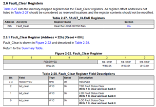
error+=LP8510_write(chip_address, 0x022, 0x07);
/*TSD Fault Status Clear; Write 1 to clear and read back 0
LSD Fault Status Clear; Write 1 to clear and read back 0
LOD Fault Status Clear; Write 1 to clear and read back 0*/
error+=LP8510_write(chip_address, 0x030, 0x01);// LED current
error+=LP8510_write(chip_address, 0x031, 0x01);
error+=LP8510_write(chip_address, 0x032, 0x01);
error+=LP8510_write(chip_address, 0x033, 0x01);
error+=LP8510_write(chip_address, 0x040, 0xFF);// PWM 100%
error+=LP8510_write(chip_address, 0x041, 0xFF);
error+=LP8510_write(chip_address, 0x042, 0xFF);
error+=LP8510_write(chip_address, 0x043, 0xFF);
return(error);
}
通过此 INIT、我可以修改 DC_CURRENT。
uint8_t LP8510_set_current(uint8_t chip_address, uint8_t current_LED_0, uint8_t current_LED_1, uint8_t current_LED_2, uint8_t current_LED_3)
{
  uint8_t error=0;

  error+=LP8510_write(chip_address, 0x030, current_LED_0);
  error+=LP8510_write(chip_address, 0x031, current_LED_1);
  error+=LP8510_write(chip_address, 0x032, current_LED_2);
  error+=LP8510_write(chip_address, 0x033, current_LED_3);

  return(error);
}

uint8_t LP8510_set_pwm(uint8_t chip_address, uint8_t pwm_LED_0, uint8_t pwm_LED_1, uint8_t pwm_LED_2, uint8_t pwm_LED_3)
{
  uint8_t error=0;

  error+=LP8510_write(chip_address, 0x040, pwm_LED_0);
  error+=LP8510_write(chip_address, 0x041, pwm_LED_1);
  error+=LP8510_write(chip_address, 0x042, pwm_LED_2);
  error+=LP8510_write(chip_address, 0x043, pwm_LED_3);

  return(error);
}

void setup()
{
  Wire.begin();

  Serial.begin(9600);
  while (!Serial);
  Serial.println("\nSerial activated");

  Serial.println(LP8510_init(LP8510_Broadcast));
  Serial.println(LP8510_set_current(LP8510_Broadcast,0x10,0x20,0x30,0x40));
  Serial.println(LP8510_set_pwm(LP8510_Broadcast,0xFF,0xFF,0xFF,0xFF));
}
LED 为0x10...0x40亮。
使用以下代码、I 读取寄存器0x300、0x301、0x303的值:
uint8_t LP8510_read(uint8_t chip_address, uint16_t register_address,uint8_t* data)
{
  uint8_t chip_address_dummy=0, register_address_dummy_8=0;
  uint16_t register_address_dummy_16=0;

  chip_address=chip_address << 2;
  chip_address=chip_address&0x7F;

  register_address_dummy_16=register_address&0x3FF;
  register_address_dummy_8=register_address_dummy_16 >> 8;

  chip_address_dummy=chip_address+register_address_dummy_8;

  register_address_dummy_8=register_address&0xFF;

  Wire.beginTransmission(chip_address_dummy);
  Wire.write(register_address_dummy_8);
  Wire.endTransmission( false );
  Wire.requestFrom(chip_address_dummy, 1, true );          // Tell slave we need to read 1byte from the current register
  if ( Wire.available() >= 1 )
  {
    *data = Wire.read();        // read that byte into 'slaveByte2' variable
  }
  return(Wire.endTransmission(true));
}


void loop()
{
  uint8_t dummy=0;
  Serial.print(LP8510_read(LP8510_Broadcast, 0x300, &dummy));
  Serial.print(" # ");
  Serial.print(dummy);
  Serial.print(" # ");
  Serial.print(LP8510_read(LP8510_Broadcast, 0x301, &dummy));
  Serial.print(" # ");
  Serial.print(dummy);
  Serial.print(" # ");
  Serial.print(LP8510_read(LP8510_Broadcast, 0x303, &dummy));
  Serial.print(" # ");
  Serial.println(dummy);
  delay(1000);
}
问题如下:
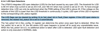
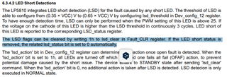
我可以短路或断开 LED、而不会更改"LED 开路检测"和"LED 短路检测"。
问题在哪里????
PWM 必须超过25、但它可以超过255? 无文档
谢谢!
此致
哈拉尔德