This thread has been locked.

If you have a related question, please click the "Ask a related question" button in the top right corner. The newly created question will be automatically linked to this question.

[参考译文] DRA821U:无法将 J7200 EVM 与 Blackhawk USB560v2系统跟踪程序调试器(BH-USB-560v2)连接

Guru**** 2362840 points
请注意,本文内容源自机器翻译,可能存在语法或其它翻译错误,仅供参考。如需获取准确内容,请参阅链接中的英语原文或自行翻译。

https://e2e.ti.com/support/processors-group/processors/f/processors-forum/1508083/dra821u-failed-to-connect-j7200-evm-with-blackhawk-usb560v2-system-tracer-debugger-bh-usb-560v2

器件型号:DRA821U

工具/软件:

您好!

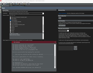
我尝试 在 CCS 12.8.1中将 Blackhawk USB560v2系统跟踪程序调试器(BH-USB-560v2)连接到 J7200 EVM。 CCS 报告的错误#-183。 我在下面附上了屏幕截图和日志。 我的 EVM 设置为无引导模式。 您能告诉我什么问题吗? 我预计该调试器开箱即用、因为 CCS 支持该调试器。

谢谢、

Charles

测试连接日志

[Start: Blackhawk XDS560v2-USB System Trace Emulator_0]

Execute the command:

%ccs_base%/common/uscif/dbgjtag.exe -f %boarddatafile% -rv -o -F inform,logfile=yes -S pathlength -S integrity

[Result]


-----[Print the board config pathname(s)]------------------------------------

C:\Users\rhlchmao\AppData\Local\TEXASI~1\
    CCS\ccs1281\0\0\BrdDat\testBoard.dat

-----[Print the reset-command software log-file]-----------------------------

This utility has selected a 560/2xx-class product.
This utility will load the program 'bh560v2u.out'.
Loaded FPGA Image: C:\ti\ccs1281\ccs\ccs_base\common\uscif\dtc_top.jbc
The library build date was 'Sep 26 2024'.
The library build time was '10:02:16'.
The library package version is '20.0.0.3178'.
The library component version is '35.35.0.0'.
The controller does not use a programmable FPGA.

An error occurred while hard opening the controller.

-----[An error has occurred and this utility has aborted]--------------------

This error is generated by TI's USCIF driver or utilities.

The value is '-183' (0xffffff49).
The title is 'SC_ERR_CTL_CBL_BREAK_FAR'.

The explanation is:
The controller has detected a cable break far-from itself.
The user must connect the cable/pod to the target.

[End: Blackhawk XDS560v2-USB System Trace Emulator_0]

  • 请注意,本文内容源自机器翻译,可能存在语法或其它翻译错误,仅供参考。如需获取准确内容,请参阅链接中的英语原文或自行翻译。

    仅供参考、板载 XDS110调试器没有此连接问题。 EVM 上的 SW3.2处于 ON 位置。 我的定制电路板存在相同的连接问题、因此我想先在 EVM 上进行验证。  

  • 请注意,本文内容源自机器翻译,可能存在语法或其它翻译错误,仅供参考。如需获取准确内容,请参阅链接中的英语原文或自行翻译。

    也请访问:-> https://e2e.ti.com/support/processors-group/processors/f/processors-forum/1178240/faq-sk-tda4vm-how-do-i-connect-the-external-debugger-blackhawk-usb560v2-xds560v2-usb-system-trace-to-the-jtag-on-the-board

    谢谢。

  • 请注意,本文内容源自机器翻译,可能存在语法或其它翻译错误,仅供参考。如需获取准确内容,请参阅链接中的英语原文或自行翻译。

    尊敬的 Praveen:

    感谢您分享这些信息、但它们不适用于我的案例。 我的 USB560v2上的两个 LED 都是绿色的、因此前两个线程的情况与我的问题不同。 我还在 Linux 计算机上尝试过、lsusb 正确检测到调试器、但测试连接仍然失败。 下面随附了日志。

    edr@RHLX0001:~$ lsusb
    Bus 002 Device 002: ID 0bda:0328 Realtek Semiconductor Corp. USB3.0-CRW
    Bus 002 Device 003: ID 0bda:0411 Realtek Semiconductor Corp. Hub
    Bus 002 Device 001: ID 1d6b:0003 Linux Foundation 3.0 root hub
    Bus 001 Device 002: ID 0bda:818b Realtek Semiconductor Corp. RTL8192EU 802.11b/g/n WLAN Adapter
    Bus 001 Device 006: ID 0b1e:0009 Electronic Warfare Assoc., Inc. (EWA) Blackhawk USB560v2 System Trace Emulator
    Bus 001 Device 003: ID 0bda:5411 Realtek Semiconductor Corp. RTS5411 Hub
    Bus 001 Device 001: ID 1d6b:0002 Linux Foundation 2.0 root hub
    

    CCS 测试连接日志:

    [Start: Blackhawk XDS560v2-USB System Trace Emulator_0]
    
    Execute the command:
    
    %ccs_base%/common/uscif/dbgjtag -f %boarddatafile% -rv -o -F inform,logfile=yes -S pathlength -S integrity
    
    [Result]
    
    -----[Print the board config pathname(s)]------------------------------------
    
    /home/edr/.ti/ccs1281/0/0/BrdDat/testBoard.dat
    
    -----[Print the reset-command software log-file]-----------------------------
    
    This utility has selected a 560/2xx-class product.
    This utility will load the program 'libbh560v2u.out'.
    Loaded FPGA Image: /home/edr/ti/ccs1281/ccs/ccs_base/common/uscif/./dtc_top.jbc
    The library build date was 'Sep 26 2024'.
    The library build time was '10:02:16'.
    The library package version is '20.0.0.3178'.
    The library component version is '35.35.0.0'.
    The controller does not use a programmable FPGA.
    
    An error occurred while hard opening the controller.
    
    [End: Blackhawk XDS560v2-USB System Trace Emulator_0]
    

  • 请注意,本文内容源自机器翻译,可能存在语法或其它翻译错误,仅供参考。如需获取准确内容,请参阅链接中的英语原文或自行翻译。

    好的、您能告诉我们为什么您没有使用板载 XDS110接口吗?

    此外、如何将  USB560v2连接到 J7200 EVM?

    我们通常使用板载 XDS110接口。 根据您的上述答案、我们可能需要检查并尝试在最后查看我们是否遇到了您提到的相同问题。  

    谢谢。

  • 请注意,本文内容源自机器翻译,可能存在语法或其它翻译错误,仅供参考。如需获取准确内容,请参阅链接中的英语原文或自行翻译。

    尊敬的 Praveen:

    我实际上想调试我没有 XDS110的定制板、但我发现 USB560v2不能与定制板一起使用。 我在 EVM 上试过、发现它也不起作用。 我通过 MIPI 60连接器将 USB560v2连接到 EVM。

  • 请注意,本文内容源自机器翻译,可能存在语法或其它翻译错误,仅供参考。如需获取准确内容,请参阅链接中的英语原文或自行翻译。

    我们试用了 Blackhawk XDS5560v2、并成功连接了 TI EVM。 测试连接日志如下所示。 您是否有额外的 XDS560v2可以试用?

    [Start: Blackhawk XDS560v2-USB System Trace Emulator_0]
    
    Execute the command:
    
    %ccs_base%/common/uscif/dbgjtag -f %boarddatafile% -rv -o -F inform,logfile=yes -S pathlength -S integrity
    
    [Result]
    
    
    -----[Print the board config pathname(s)]------------------------------------
    
    /home/a0389345local/.ti/ccs1250/0/0/BrdDat/
        testBoard.dat
    
    -----[Print the reset-command software log-file]-----------------------------
    
    This utility has selected a 560/2xx-class product.
    This utility will load the program 'libbh560v2u.out'.
    Loaded FPGA Image: /home/a0389345local/ti/ccs1250/ccs/ccs_base/common/uscif/./dtc_top.jbc
    The library build date was 'Sep  6 2023'.
    The library build time was '14:41:42'.
    The library package version is '9.13.0.00201'.
    The library component version is '35.35.0.0'.
    The controller does not use a programmable FPGA.
    The controller has a version number of '6' (0x00000006).
    The controller has an insertion length of '0' (0x00000000).
    The cable+pod has a version number of '8' (0x00000008).
    The cable+pod has a capability number of '7423' (0x00001cff).
    This utility will attempt to reset the controller.
    This utility has successfully reset the controller.
    
    -----[Print the reset-command hardware log-file]-----------------------------
    
    The scan-path will be reset by toggling the JTAG TRST signal.
    The controller is the Nano-TBC VHDL.
    The link is a 560-class second-generation-560 cable.
    The software is configured for Nano-TBC VHDL features.
    The controller will be software reset via its registers.
    The controller has a logic ONE on its EMU[0] input pin.
    The controller has a logic ONE on its EMU[1] input pin.
    The controller will use falling-edge timing on output pins.
    The controller cannot control the timing on input pins.
    The scan-path link-delay has been set to exactly '2' (0x0002).
    The utility logic has not previously detected a power-loss.
    The utility logic is not currently detecting a power-loss.
    Loaded FPGA Image: /home/a0389345local/ti/ccs1250/ccs/ccs_base/common/uscif/./dtc_top.jbc
    
    -----[The log-file for the JTAG TCLK output generated from the PLL]----------
    
      Test  Size   Coord      MHz    Flag  Result       Description
      ~~~~  ~~~~  ~~~~~~~  ~~~~~~~~  ~~~~  ~~~~~~~~~~~  ~~~~~~~~~~~~~~~~~~~
        1   none  - 01 00  500.0kHz   -    similar      isit internal clock
        2   none  - 01 09  570.3kHz   -    similar      isit internal clock
        3     64  - 01 00  500.0kHz   O    good value   measure path length
        4     16  - 01 00  500.0kHz   O    good value   auto step initial
        5     16  - 01 0D  601.6kHz   O    good value   auto step delta
        6     16  - 01 1C  718.8kHz   O    good value   auto step delta
        7     16  - 01 2E  859.4kHz   O    good value   auto step delta
        8     16  + 00 02  1.031MHz   O    good value   auto step delta
        9     16  + 00 0F  1.234MHz   O    good value   auto step delta
       10     16  + 00 1F  1.484MHz   O    good value   auto step delta
       11     16  + 00 32  1.781MHz   O    good value   auto step delta
       12     16  + 01 04  2.125MHz   O    good value   auto step delta
       13     16  + 01 11  2.531MHz   O    good value   auto step delta
       14     16  + 01 21  3.031MHz   O    good value   auto step delta
       15     16  + 01 34  3.625MHz   O    good value   auto step delta
       16     16  + 02 05  4.312MHz   O    good value   auto step delta
       17     16  + 02 13  5.188MHz   O    good value   auto step delta
       18     16  + 02 23  6.188MHz   O    good value   auto step delta
       19     16  + 02 37  7.438MHz   O    good value   auto step delta
       20     16  + 03 07  8.875MHz   O    good value   auto step delta
       21     16  + 03 15  10.62MHz   O    good value   auto step delta
       22     16  + 03 1E  11.75MHz  {O}   good value   auto step delta
       23     64  + 02 3E  7.875MHz   O    good value   auto power initial
       24     64  + 03 0E  9.750MHz   O    good value   auto power delta
       25     64  + 03 16  10.75MHz   O    good value   auto power delta
       26     64  + 03 1A  11.25MHz   O    good value   auto power delta
       27     64  + 03 1C  11.50MHz   O    good value   auto power delta
       28     64  + 03 1D  11.62MHz   O    good value   auto power delta
       29     64  + 03 1D  11.62MHz   O    good value   auto power delta
       30     64  + 03 13  10.38MHz  {O}   good value   auto margin initial
    
    The first internal/external clock test resuts are:
    The expect frequency was 500000Hz.
    The actual frequency was 499872Hz.
    The delta frequency was 128Hz.
    
    The second internal/external clock test resuts are:
    The expect frequency was 570312Hz.
    The actual frequency was 569976Hz.
    The delta frequency was 336Hz.
    
    In the scan-path tests:
    The test length was 2048 bits.
    The JTAG IR length was 4 bits.
    The JTAG DR length was 1 bits.
    
    The IR/DR scan-path tests used 30 frequencies.
    The IR/DR scan-path tests used 500.0kHz as the initial frequency.
    The IR/DR scan-path tests used 11.75MHz as the highest frequency.
    The IR/DR scan-path tests used 10.38MHz as the final frequency.
    
    -----[Measure the source and frequency of the final JTAG TCLKR input]--------
    
    The frequency of the JTAG TCLKR input is measured as 10.37MHz.
    
    The frequency of the JTAG TCLKR input and TCLKO output signals are similar.
    The target system likely uses the TCLKO output from the emulator PLL.
    
    -----[Perform the standard path-length test on the JTAG IR and DR]-----------
    
    This path-length test uses blocks of 64 32-bit words.
    
    The test for the JTAG IR instruction path-length succeeded.
    The JTAG IR instruction path-length is 4 bits.
    
    The test for the JTAG DR bypass path-length succeeded.
    The JTAG DR bypass path-length is 1 bits.
    
    -----[Perform the Integrity scan-test on the JTAG IR]------------------------
    
    This test will use blocks of 64 32-bit words.
    This test will be applied just once.
    
    Do a test using 0xFFFFFFFF.
    Scan tests: 1, skipped: 0, failed: 0
    Do a test using 0x00000000.
    Scan tests: 2, skipped: 0, failed: 0
    Do a test using 0xFE03E0E2.
    Scan tests: 3, skipped: 0, failed: 0
    Do a test using 0x01FC1F1D.
    Scan tests: 4, skipped: 0, failed: 0
    Do a test using 0x5533CCAA.
    Scan tests: 5, skipped: 0, failed: 0
    Do a test using 0xAACC3355.
    Scan tests: 6, skipped: 0, failed: 0
    All of the values were scanned correctly.
    
    The JTAG IR Integrity scan-test has succeeded.

  • 请注意,本文内容源自机器翻译,可能存在语法或其它翻译错误,仅供参考。如需获取准确内容,请参阅链接中的英语原文或自行翻译。

    尊敬的 Praveen:

    感谢您的检查。 我没有任何多余的,但我会得到另一个,并重试.

  • 请注意,本文内容源自机器翻译,可能存在语法或其它翻译错误,仅供参考。如需获取准确内容,请参阅链接中的英语原文或自行翻译。

    好的、我们现在将关闭该主题。