工具与软件:
当前的 Linux SDK 文档提供了设置调度流量增强(EST)的示例: https://software-dl.ti.com/processor-sdk-linux/esd/AM64X/latest/exports/docs/linux/Foundational_Components Kernel_Drivers Network/CPSW-EST.html
但是、该示例很难理解和分析。
是否有更简单的方法来测试 EST 并分析结果?
This thread has been locked.
If you have a related question, please click the "Ask a related question" button in the top right corner. The newly created question will be automatically linked to this question.
工具与软件:
当前的 Linux SDK 文档提供了设置调度流量增强(EST)的示例: https://software-dl.ti.com/processor-sdk-linux/esd/AM64X/latest/exports/docs/linux/Foundational_Components Kernel_Drivers Network/CPSW-EST.html
但是、该示例很难理解和分析。
是否有更简单的方法来测试 EST 并分析结果?
在 Linux 中设置 EST/TAS 简单示例的步骤
1.配置 EST 计划
在这个简单的示例中、我们将设置两个流量类别(TC)、目标是1毫秒的周期时间。 在本例中、线速率需要为1Gbps。
此配置意味着 TC1限制为20Mbps、TC0限制为980Mbps。
下面的脚本提供了有关如何设置上述计划的示例。
est_2_queue_ex.sh
#Must bring down all connected interfaces to modify interface properties
ip link set dev eth0 down
ip link set dev eth1 down
sleep 2

#Configure 8 TX queues for eth0
ethtool -L eth0 tx 8

#Show current eth0 properties
ethtool -l eth0

#Driver doesn't enable EST in round-robin mode, by default this is off
ethtool --set-priv-flags eth0 p0-rx-ptype-rrobin off

#Show current round-robin settings for eth0
ethtool --show-priv-flags eth0

#Bring all connected interfaces up
ip link set dev eth0 up
ip link set dev eth1 up
sleep 3

#Sets up the EST schedule to map all 8 HW TX Queues
tc qdisc replace dev eth0 parent root handle 100 taprio num_tc 8 map 0 1 2 3 4 5 6 7 0 0 0 0 0 0 0 0 queues 1@0 1@1 1@2 1@3 1@4 1@5 1@6 1@7 base-time 0000 sched-entry S 2 20000 sched-entry S 1 980000 flags 2
#sched-entry S 2 --> 5002 --> priority/queue 1
#sched-entry S 1 --> 5001 --> priority/queue 0
#Q7 is the highest priority Queue and Q0 is the lowest priority

#To enable the classifier
tc qdisc add dev eth0 clsact

#Show current EST schedule
tc qdisc show dev eth0

#To configure the skb priority to deliver frames to specific hardware queues?
tc filter add dev eth0 egress protocol ip prio 1 u32 match ip dport 5002 0xffff action skbedit priority 1
tc filter add dev eth0 egress protocol ip prio 1 u32 match ip dport 5001 0xffff action skbedit priority 0

#Show filters applied to packets leaving the eth0 interface
tc filter show dev eth0 egress
----------------------------------------------------------------------------------------------------------------------------------------------------------------------------------------------------------------
2.选择数据包生成器
有几个不同的基于 Linux 的数据包生成器、每个数据包生成器在用于 EST 示例时都各有优缺点。
为了更轻松地分析 EST 示例的结果、请选择数据包生成器、让用户可以在发送的每个数据包之间指定特定的间隔。
下面列出了一些基于 Linux 的数据包生成器以及在 EST 示例中使用时的优缺点。
| 数据包发生器 | 优点 | 缺点 |
| iperf3. | 已包含在 TI 处理器 SDK Linux 中 | 不允许用户指定数据包传输间隔 |
| 图3 | 允许用户指定数据包传输间隔 |
TI Processor SDK Linux 中不包含 必须单独构建和包含 或者必须通过 TI Debian SDK 上的"sudo apt install hping3"进行安装 |
| nping | 允许用户指定数据包传输间隔 |
TI Processor SDK Linux 中不包含 必须单独构建和包含 或者必须通过 TI Debian SDK 上的"sudo apt install nmape"进行安装 |
| pktgen |
Linux 内核的数据包生成器工具、因此只需在内核配置中启用 CONFIG_NET_PKTGEN 可用于以特定间隔或突发方式发送数据包 高速发送大量数据包 |
pktgen 发送的数据包被标记为"PKTGEN"数据包、而不是 UDP 或 TCP 数据包 需要找出正确的 EST 配置来控制 PKTGEN 数据包 |
为了简单和方便访问,我们将使用 iperf3客户端的两个实例模拟以下内容
要确定模拟 TC1的正确 iperf3客户端配置:
| 选择小于最大传输单元(MTU)大小的帧大小、不包括标头字节(小于1472字节) |
1个帧= 1400个字节 |
| 使用选定的帧大小计算带宽 |
1帧/毫秒= 1400字节/毫秒= 11200位/毫秒= 1200000位/秒= 11.2兆位/秒-->四舍五入至12Mbps |
| 检查计算得出的带宽是否未超过20Mbps |
12Mbps < 20Mbps |
| 选择数据包生成的持续时间 |
3秒 |
TC1:iperf3 -c -u -b12M -p 5002 -L1400 -T3&
TC0: iperf3 -c -p 5001-t3&
----------------------------------------------------------------------------------------------------------------------------------------------------------------------------------------------------------------
3.硬件设置和运行命令
首先、设置通过一根以太网电缆连接的两个器件(例如 AM64x EVM)。
DUT1 <--->DUT2
其次、运行 est_2_queue_ex.sh 脚本以在 DUT1上设置 EST 调度。
./est_2_queue_ex.sh
第三、在 DUT2上设置 iperf3服务器。
iperf3 -s -p5001 &
iperf3 -s -p5002 &
最后、在 DUT1上运行 iperf3客户端。
root@am64xx-evm:~# cat iperf_est.sh
ipaddr=$1

if [ "$#" != "1" ]
then
        echo "$0 <ipaddr>"
        exit
fi

iperf3 -c $ipaddr -u -b12M -p 5002 -l1400 -t3&
iperf3 -c $ipaddr -p 5001 -t3&
root@am64xx-evm:~# sh iperf_est.sh 192.168.1.11 如何分析 EST/TAS 结果
1.默认配置
a.使用 Wireshark 等以太网攻丝工具捕获从 DUT1发送到 DUT2的数据包。 使用 Profishark 设备获得更准确的计时结果。
此处的"默认配置"是指本常见问题解答第一部分中的配置步骤。
b.一旦捕获到数据包、对其进行过滤、使其仅过滤为 TC1数据包、即发送到端口5002的 UDP 数据包。 (即 Wireshark 中的"udp.dstport==5002")。
c.在 Wireshark 中将时间显示为"上次显示数据包后的秒数"(即"View -> Time Display Format (查看->时间显示格式))
d.将 pcap 文件导出为 csv 文件并与 Excel 一起打开(或在 Linux PC 上打开 LibreCalc)
e.在 Excel 中基于时间(间隔)创建直方图


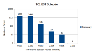
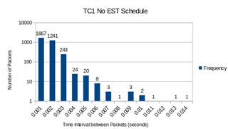
左侧的直方图显示了 EST 调度下每个 TC1数据包之间的时间间隔。 右侧的直方图显示了每个 TC1数据包(无 EST 调度)之间的时间间隔。
在 EST 调度下、我们预计大多数 TC1数据包在每个数据包之间的时间间隔<= 0.001秒(1ms)、因为这是我们配置 EST 的周期时间。
但是、如左侧直方图所示、仍有许多数据包大于0.001秒。 这可能归因于 iperf3不是一个可以控制每个数据包发送的间隔的数据包生成器。 而是根据所配置的带宽、数据包大小和线路速率以突发方式发送数据包。 这意味着、在1ms 的周期时间内可能不会发送 TC1数据包(只要在1Gbps 线路速率上满足总共12Mbps 和1400字节的要求)。
使用另一个允许控制发送每个数据包的时间间隔的数据包生成器可能会显示更好的结果。
2.优化配置(以获得更好的结果)
如"默认配置"中所述、主要问题在于 iperf3不是用于测试和分析 EST 调度的最佳数据包生成器工具。
为了缩短计时间隔、请进行以下更改
DUT1命令
root@am64xx-evm:~# phc2sys -a -r -transportSpecific=1 &
root@am64xx-evm:~# cat iperf_est.sh
#iperf3 -c 172.168.1.1 -u -b900M  -p 5001 -l1472 -t10 &

ipaddr=$1

if [ "$#" != "1" ]
then
        echo "$0 <ipaddr>"
        exit
fi

chrt -f 60 iperf3 -c $ipaddr -u -b20M -p 5002 -l1400 -t3&
chrt -f 60 iperf3 -c $ipaddr -p 5001 -t3&
root@am64xx-evm:~# sh iperf_est.sh 192.168.1.11
DUT2命令
phc2sys -a -r -transportSpecific=1 &
iperf3 -s -p5001&
chrt -f 60 iperf3 -s -p5002&

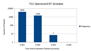
通过上述三种更改、每个 TC1数据包的时间间隔更接近0.001秒内。 但是、由于仍然有许多大于0.001秒的 TC1数据包、这表明使用 iperf3仍然不是测试 EST 调度效果的最佳工具。
可能值得尝试其他数据包生成器工具或直接对目标流量运行 EST 调度、并使用此处的步骤分析 EST 调度的影响。
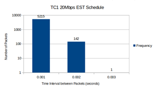
注意:下面是 仅将 iperf3带宽更改为20Mbps 的直方图。 增加 TC2的 iperf3带宽有助于获得更好的结果来分析 EST 调度。
