This thread has been locked.

If you have a related question, please click the "Ask a related question" button in the top right corner. The newly created question will be automatically linked to this question.

[参考译文] AFE58JD48EVM:AFE58JD48EVM

Guru**** 1810440 points
Other Parts Discussed in Thread: TSW14J50EVM, AFE58JD48EVM, AFE58JD48
请注意,本文内容源自机器翻译,可能存在语法或其它翻译错误,仅供参考。如需获取准确内容,请参阅链接中的英语原文或自行翻译。

https://e2e.ti.com/support/tools/simulation-hardware-system-design-tools-group/sim-hw-system-design/f/simulation-hardware-system-design-tools-forum/1425321/afe58jd48evm-afe58jd48evm

器件型号:AFE58JD48EVM
《主题中讨论的其他器件:TSW14J50EVM》、、 AFE58JD48

工具与软件:

你好


我已将 TSW14J50EVM 连接到 AFE58JD48EVM 。


我可以从 HDSC Pro 对波形进行采样 (版本5.20)  但触发选项不起作用。
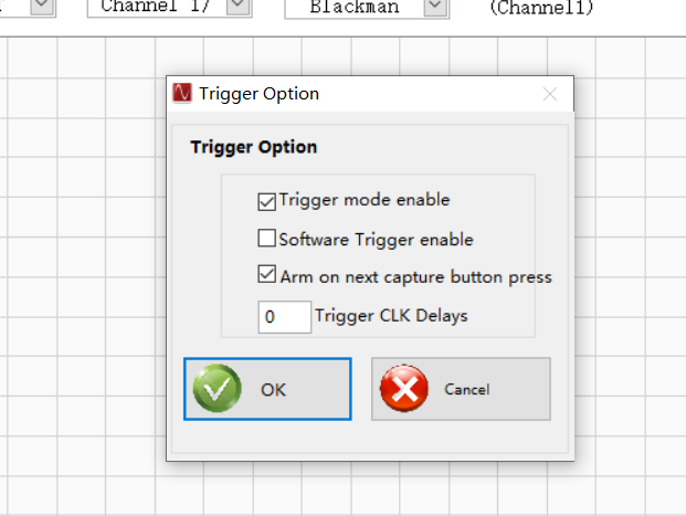
 

触发选项的配置如下:


我将一个3.3V 100ns 宽触发脉冲馈送到 TRIG_IN SMA 连接器、但捕获无法开始。 HDSC 持续显示"已触发但未响应我的触发。


选择"Trigger mode enable"和"ARM on next capture button press"并点击"Generate trigger"后、HSDC 会等待一段时间、并显示"No trigger occurred"。


我尝试了以下配置、但都失败了 :

AFE58JD48_Custom_PLL_MODE_40x_No Demod_Sub、

固件 AFE58JD48.ini


请告诉我、若要使外部触发器正常工作、需要采取哪些措施


  • 请注意,本文内容源自机器翻译,可能存在语法或其它翻译错误,仅供参考。如需获取准确内容,请参阅链接中的英语原文或自行翻译。

    Feng、

    遗憾的是、TSW14J50不支持具有自动重新 ARM 的外部触发、 因为固件未 实现该功能。

    另外请注意、TRIG-IN 等数字输入信号应该为1.8Vpp。

    有关更多信息、请参阅以下线程:


    https://e2e.ti.com/support/data-converters-group/data-converters/f/data-converters-forum/1042016/tsw14j56evm-hsdc-pro-auto-re-arm-trigger-functionality

    https://e2e.ti.com/support/data-converters-group/data-converters/f/data-converters-forum/1400218/tsw14j50evm-hsdc-pro-software---auto-re-arm-trigger-option-unavailable


    对此可能造成的任何不便、我们深表歉意。

  • 请注意,本文内容源自机器翻译,可能存在语法或其它翻译错误,仅供参考。如需获取准确内容,请参阅链接中的英语原文或自行翻译。

    Shane Aspenwall,

    我们不使用带自动复位功能的外部触发器。 我们需要接收来自 TSW14J50EVM 上的其他器件或信号发生器的外部触发、并且能够正常工作。 根据上述步骤、显示的最终结果为"未发生触发"。 我将向您发送我使用的固件、您能告诉我问题出在哪里吗?

    [ADC]
    
    Interface name="TSW14J50RX_FIRMWARE"
    Number of channels=16	
    Channel Pattern=1,2,5,6,9,10,13,14,3,4,7,8,11,12,15,16
    Data Postprocessing=0:2,1:8192
    
    \\operation:operand
    \\operaion
    \\0=bit shift
    \\1=xor
    \\2=and
    \\3=or
    \\4=not
    \\operand
    \\value(+ve if bitshift by right and -ve if bitshift by left)
    \\E.g 0:-2,1:1024
    \\bitshift by left 2 times and then xor by 1024
    
    Number of Bits=16
    Max sample Rate=125000000
    Register_Config="-"	
    \\[Register Address]:[Register Value]:[Number of Bytes to be sent as]
    DLL Version=1.0
    Read EVM Setup Procedure="EVM Setup Procedure not available"	
    \\use <> as delimiter for newline
    Menu Enable="Trigger Option"
    Device GUI EXE Name=AFE58JD48 EVM 
    Device GUI EXE Port Number=6640 
    Device GUI EXE Path=..\AFE58JD48 EVM
    
    [Version 1.0]
    
    
    JESD IP Core_L=4
    JESD IP Core_M=4
    JESD IP Core_F=8
    JESD IP Core_K=3
    JESD IP Core_N=14
    JESD IP Core_NTotal=16
    
    JESD IP Core_CS=0
    JESD IP Core_HD=0
    JESD IP Core_S=1
    JESD IP Core_SCR=0
    JESD IP Core_Tailbits=0
    JESD IP Core_LaneSync=1
    JESD IP Core_Subclass=1
    JESD IP Core_JESDV=1
    
    \\Sysref Based Master Slave Trigger = 1
    	
    MIF Config= 0.5G to 8.0G:RX:RX_PMA_x40
    \\List of Lane Rate Range,PLL Type and their MIF File names that needs to be configured,separated by ":"
    \\These MIF Files need to be present under MIF Files Folder
    Fabric PLL Counter = 0.5G to 8.0G:0x080202
    Invert Sync Polarity = 0	
     \\Invert Sync polarity, 1:invert; 0: do not invert
    Invert Serdes Data = 0 	
     \\Invert Serdes Data, 1:invert; 0: do not invert
    Transceiver Mode = 0  	
    \\1:xcvr mode; 0: TX/RX only mode
    Lane Mapping=lane0:0,lane1:2,lane2:4,lane3:6	
    \\Lane pattern for the LMF modes
    Group 128 bits Flag = 1
    \\Is Capture Trigger SMA = 1
    Export Parameters = ADC Input Target Frequency
    [ADC]
    
    Interface name="TSW14J50RX_FIRMWARE"
    Number of channels=16	
    Channel Pattern=1,2,3,4,5,6,7,8,9,10,11,12,13,14,15,16
    Data Postprocessing=1:32768
    
    \\operation:operand
    \\operaion
    \\0=bit shift
    \\1=xor
    \\2=and
    \\3=or
    \\4=not
    \\operand
    \\value(+ve if bitshift by right and -ve if bitshift by left)
    \\E.g 0:-2,1:1024
    \\bitshift by left 2 times and then xor by 1024
    
    Number of Bits=16
    Max sample Rate=125000000
    Register_Config="-"	
    \\[Register Address]:[Register Value]:[Number of Bytes to be sent as]
    DLL Version=1.0
    Read EVM Setup Procedure="EVM Setup Procedure not available"	
    \\use <> as delimiter for newline
    Menu Enable="Trigger Option"
    [Version 1.0]
    
    
    JESD IP Core_L=8
    JESD IP Core_M=5
    JESD IP Core_F=4
    JESD IP Core_K=8
    JESD IP Core_N=16
    JESD IP Core_NTotal=16
    
    JESD IP Core_CS=0
    JESD IP Core_HD=0
    JESD IP Core_S=1
    JESD IP Core_SCR=0
    JESD IP Core_Tailbits=0
    JESD IP Core_LaneSync=1
    JESD IP Core_Subclass=1
    JESD IP Core_JESDV=1
    
    \\Sysref Based Master Slave Trigger = 1
    	
    MIF Config= 0.5G to 8.0G:RX:RX_PMA_x40
    \\List of Lane Rate Range,PLL Type and their MIF File names that needs to be configured,separated by ":"
    \\These MIF Files need to be present under MIF Files Folder
    Fabric PLL Counter = 0.5G to 8.0G:0x080202
    Invert Sync Polarity = 0	
     \\Invert Sync polarity, 1:invert; 0: do not invert
    Invert Serdes Data = 0 	
     \\Invert Serdes Data, 1:invert; 0: do not invert
    Transceiver Mode = 0  	
    \\1:xcvr mode; 0: TX/RX only mode
    Lane Mapping=lane0:3,lane1:2,lane2:1,lane3:0, lane4:5, lane5:4, lane6:7, lane7:6	
    \\Lane pattern for the LMF modes
    Group 128 bits Flag = 1
    \\Is Capture Trigger SMA = 1
    

    此致、

    冯涛.

  • 请注意,本文内容源自机器翻译,可能存在语法或其它翻译错误,仅供参考。如需获取准确内容,请参阅链接中的英语原文或自行翻译。

    冯涛

    根据我的理解、每次捕获之间只需要一次触发。 我复制了您的配置(TSW14J50EVM + AFE58JD48EVM)。 尝试 以下操作:


    1.启用触发模式

    2.将波形发生器源连接到 J13"EXT TRIG"

    3、设置 波形源——10us 脉宽、1.8Vpp、1Hz。 输出阻抗应设置为1M 或 Hi-Z输出关闭 . 在源关闭的情况下读取 DDR 应会导致"No trigger occurred"错误。 如果 DDR 存储器已经采集到数据、则可能需要按两次。

    4.点击"Read DDR Memory"。 然后、激活触发器。


    为了验证触发开始捕获、我将触发输出拆分为 CH10的输入并捕获瞬态。 该器件具有 LPF、因此脉冲不是方波。

    希望这能解决您的问题!