This thread has been locked.

If you have a related question, please click the "Ask a related question" button in the top right corner. The newly created question will be automatically linked to this question.

[参考译文] CC1310:使用信标块化时的功耗高于调用 SLEEP 时的功耗。

Guru**** 2463330 points


请注意,本文内容源自机器翻译,可能存在语法或其它翻译错误,仅供参考。如需获取准确内容,请参阅链接中的英语原文或自行翻译。

https://e2e.ti.com/support/wireless-connectivity/sub-1-ghz-group/sub-1-ghz/f/sub-1-ghz-forum/1534136/cc1310-power-consumption-higher-when-using-semaphore-to-block-than-calling-sleep

器件型号:CC1310


工具/软件:

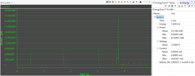
我有一个要求低功耗的器件。  我想在睡眠时尽可能少地使用电源。  将设备置于待机模式的示例程序只调用 sleep() 函数。  我已经确认、这会使器件进入睡眠状态、消耗大约 10 μ A 的电流。  如果我不想调用睡眠、而是依靠信标来等待任务、那么我的功耗为 300uA。  然而、调用睡眠函数不能通过中断来唤醒任务。 我可以执行中断、但一旦 ISR 结束、器件在剩余的睡眠时间内恢复睡眠状态。

在调用睡眠模式时、如何将功耗降至 10uA、并在 ISR 触发时让我的设备继续执行任务?

  • 请注意,本文内容源自机器翻译,可能存在语法或其它翻译错误,仅供参考。如需获取准确内容,请参阅链接中的英语原文或自行翻译。

    我不知道在等待信标时为什么电流消耗为 300uA。 得到的电流低于 1uA、这是待机时的预期功耗。

    我从 SDK 中获取了 rfPacketTX 示例、并对其进行了修改、以等待在数据包之间按下按钮、而不是调用睡眠模式。

    代码如下:

    /* Standard C Libraries */
    #include <stdlib.h>
    #include <unistd.h>
    
    /* TI Drivers */
    #include <ti/drivers/rf/RF.h>
    #include <ti/drivers/PIN.h>
    #include <ti/drivers/pin/PINCC26XX.h>
    
    /* BIOS Header files */
    #include <ti/sysbios/BIOS.h>
    #include <ti/sysbios/knl/Semaphore.h>
    #include <ti/sysbios/knl/Task.h>
    
    /* Driverlib Header files */
    #include DeviceFamily_constructPath(driverlib/rf_prop_mailbox.h)
    
    /* Board Header files */
    #include "Board.h"
    #include "smartrf_settings/smartrf_settings.h"
    
    /***** Defines *****/
    
    /* Packet TX Configuration */
    #define PAYLOAD_LENGTH      30
    
    /***** Variable declarations *****/
    static RF_Object rfObject;
    static RF_Handle rfHandle;
    
    static PIN_Handle buttonPinHandle;
    static PIN_State buttonPinState;
    
    static uint8_t packet[PAYLOAD_LENGTH];
    static uint16_t seqNumber;
    
    static Semaphore_Struct txSemaphore;
    static Semaphore_Handle txSemaphoreHandle;
    
    PIN_Config buttonPinTable[] = {
        Board_PIN_BUTTON0 | PIN_INPUT_EN | PIN_PULLUP | PIN_IRQ_NEGEDGE,
        PIN_TERMINATE
    };
    
    void buttonCallbackFunction(PIN_Handle handle, PIN_Id pinId) {
    
        /* Simple debounce logic, only toggle if the button is still pushed (low) */
        CPUdelay((uint32_t)((48000000/3)*0.050f));
        if (!PIN_getInputValue(pinId)) {
            /* Post TX semaphore to TX task */
            Semaphore_post(txSemaphoreHandle);
        }
    }
    
    void *mainThread(void *arg0)
    {
        RF_Params rfParams;
        RF_Params_init(&rfParams);
    
        Semaphore_construct(&txSemaphore, 0, NULL);
        txSemaphoreHandle = Semaphore_handle(&txSemaphore);
    
        buttonPinHandle = PIN_open(&buttonPinState, buttonPinTable);
    
        PIN_Status status = PIN_registerIntCb(buttonPinHandle, &buttonCallbackFunction);
    
        RF_cmdPropTx.pktLen = PAYLOAD_LENGTH;
        RF_cmdPropTx.pPkt = packet;
        RF_cmdPropTx.startTrigger.triggerType = TRIG_NOW;
    
        rfHandle = RF_open(&rfObject, &RF_prop, (RF_RadioSetup*)&RF_cmdPropRadioDivSetup, &rfParams);
    
        RF_postCmd(rfHandle, (RF_Op*)&RF_cmdFs, RF_PriorityNormal, NULL, 0);
    
        while(1)
        {
            packet[0] = (uint8_t)(seqNumber >> 8);
            packet[1] = (uint8_t)(seqNumber++);
            uint8_t i;
            for (i = 2; i < PAYLOAD_LENGTH; i++)
            {
                packet[i] = rand();
            }
    
            RF_runCmd(rfHandle, (RF_Op*)&RF_cmdPropTx, RF_PriorityNormal, NULL, 0);
    
            RF_yield(rfHandle);
    
            Semaphore_pend(txSemaphoreHandle, BIOS_WAIT_FOREVER);
        }
    }

    使用能量曲线、最低电流消耗(待机)显示为 0、因为 ET 无法测量小于 1uA 的电流

    峰值是待机模式下的重新充电脉冲、然后有一个 TX

    Siri

  • 请注意,本文内容源自机器翻译,可能存在语法或其它翻译错误,仅供参考。如需获取准确内容,请参阅链接中的英语原文或自行翻译。

    Siri、

    感谢您的答复。  我看到了一些不同的东西。  我复制了您的程序并将其放入我的电路板中、我将获得 300uA 至 400uA 的绘图。  我能得到它下面的唯一方法是调用 sleep (),这是从 PIN_STANDBY 示例中获取的。  睡眠是否会导致其进入不同状态?

  • 请注意,本文内容源自机器翻译,可能存在语法或其它翻译错误,仅供参考。如需获取准确内容,请参阅链接中的英语原文或自行翻译。

    编号 上述代码和 PIN_STANDBY 示例都将器件置于待机状态。

    如果您使用的代码与我使用的代码完全相同、并且电流消耗没有相同、则硬件中必须存在差异。

    您是否在运行与 LP 不同的您自己的硬件?

    所谓睡眠模式时、您说电流消耗更低、达到 400us、但有多低?

    待机电流应小于 1us。

    您是否看到重新充电的脉冲、这表明您的设备处于待机状态?

    Siri

  • 请注意,本文内容源自机器翻译,可能存在语法或其它翻译错误,仅供参考。如需获取准确内容,请参阅链接中的英语原文或自行翻译。

    问题已解决。 感谢你的帮助。  它又使用 RF_Yield 关闭了射频。  我使用的是 Easylink、它似乎没有在其 API 中调用 RF_Yield 的函数。  所以、我添加了一个、然后在发送后调用该函数、然后再暂停在信标上。  这大大降低了器件等待时的功耗。