请注意,本文内容源自机器翻译,可能存在语法或其它翻译错误,仅供参考。如需获取准确内容,请参阅链接中的英语原文或自行翻译。
器件型号:CC1101 大家好、
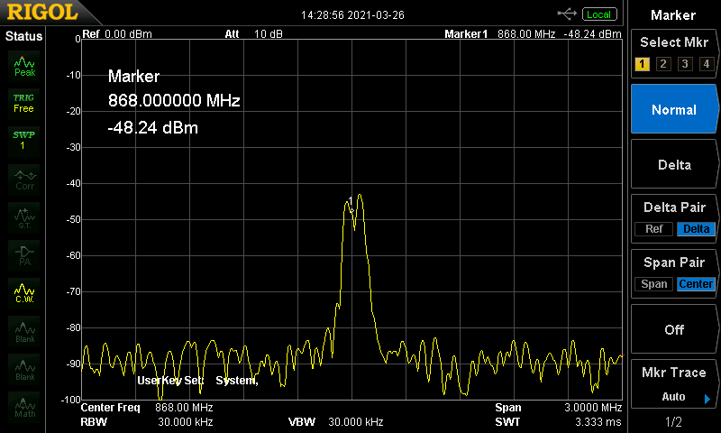
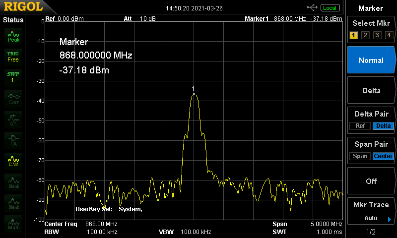
我是一名学士学生、目前正在从事智能房间预订系统的工作。 应显示的数据将使用868MHz CC1101射频收发器发送。 不幸的是、我无法使数据传输可靠地工作。 我想我可以毫无问题地发送数据、通过将 IOCFG2设置为0x06、我可以在 GDO2上接收同步状态。 我还能够使用 SDR 和网络分析器查看数据。 但是、当我从 FIFO 读取数据时、即使 CRC 处于活动状态、它也是完全无用的。 我尝试寻找某种模式、但找不到任何东西。
我负责发送和接收 TI 提供的示例代码数据(如下论坛文章中所述: e2e.ti.com/.../cc1101-how-to-use-cc1101 )、但必须对其进行修改才能与我使用的控制器配合使用。 CC1101的配置使用针对灵敏度进行优化的默认76.8kBaud 配置文件直接从射频工作室导出。
我尝试过的 PCB 是一些中国 PCB、在这里我用 DigiKey 的原厂芯片、Mibot 的分线 PCB 以及使用 Johanson Tech 平衡-非平衡变压器和天线的定制 PCB 替换了芯片。 所有 PCB 都可以相互通信、但接收到的数据不会改变。
我要发送的数据与 TI 的示例代码中的数据几乎相同、我只添加了一些静态变量、以使接收到的数据更易读、并减小数据包大小。
是否有人知道我的问题可能是什么?
提前感谢。
printf("\n\n\n- = - = - = - = - = - = -\r\n");
printf("Register values acquired through the help of TI RFstudio\r\n");

CC1101_Init();

while (1)
	{

//		for(uint8_t counter = 0; counter < 0x2F; counter++)
//		{
//			printf("The register 0x%02X is set to: 0x%02X\r\n", counter, CC1101_SpiReadReg(counter));
//		}


		//Receiver code
		if(!HAL_GPIO_ReadPin(btn0_GPIO_Port, btn0_Pin))										//If the button is not pressed on boot
		{
			printf("RX!\r\n\r\n");															//Show the user that RX mode has been selected and start the RX init

			uint8_t		rxBuffer[64] = {0};													//Init an empty rxBuffer for the received data
			uint8_t		rxBytes;															//Init a variable with the amount of bytes in the RX FIFO
			uint8_t		marcstate;															//Init a variable with the current CC1101 state

			CC1101_SpiCmdStrobe(CC1101_SRX);												//Set the CC1101 into RX mode

			while(1)
			{
				if(HAL_GPIO_ReadPin(rfGDO2_GPIO_Port, rfGDO2_Pin))							//If GDO2 is high, indicating that a packet has been received
				{

					while(HAL_GPIO_ReadPin(rfGDO2_GPIO_Port, rfGDO2_Pin));					//As long as the device is still receiving, wait

					rxBytes = CC1101_SpiReadReg(CC1101_RXBYTES);							//Read number of bytes in RX FIFO

					if(rxBytes != 0)														//Check that we have bytes in FIFO
					{
						if(rxBytes & 0x80)													//Check for RX FIFO overflow (MSB of RXBYTES)
						{
							CC1101_SpiCmdStrobe(CC1101_SFRX);								//Flush RX FIFO
						}
						else
						{
							CC1101_SpiReadBurstReg(CC1101_RXFIFO , rxBuffer, rxBytes);		//Read n bytes from RXFIFO

							//Check CRC OK (CRC_OK: bit7 in second status byte)
							//This assumes status bytes are appended in RX_FIFO
							//(PKTCTRL1.APPEND_STATUS = 1)
							//If CRC is disabled the CRC_OK field will read 1
							if(rxBuffer[rxBytes - 1] & 0x80)
							{
								printf("The received #%d packet is:\r\n", rxPacketCounter);
								for(uint8_t i = 0; i < PKTLEN; i++)
								{
									printf("0x%02X\r\n", rxBuffer[i]);
								}
								printf("\r\n\r\n");

								//Update packet counter
								rxPacketCounter++;
							}
						}
					}

					//Set radio back in RX
					CC1101_SpiCmdStrobe(CC1101_SRX);

				}
			}
		}


		//Transmitter code
		if(HAL_GPIO_ReadPin(btn0_GPIO_Port, btn0_Pin))										//If the button is pressed on boot
		{
			printf("TX!\r\n\r\n");															//Show the user that RX mode has been selected and start the TX init

			uint8_t txBuffer[PKTLEN + 1] = {0};												//Initialize packet buffer of size PKTLEN + 1

			txBuffer[3] = 0xAA;
			txBuffer[4] = 0x55;
			txBuffer[5] = 0x00;
			txBuffer[6] = 0xFF;

			while(1)
			{
				if(HAL_GPIO_ReadPin(btn0_GPIO_Port, btn0_Pin))								//Wait for a button push
				{
					do
					{
						txPacketCounter++;													//Update packet counter

						// Create a random packet with PKTLEN + 2 byte packet
						// counter + n x random bytes
						txBuffer[0] = PKTLEN;                           					//Length byte
						txBuffer[1] = (uint8_t) (txPacketCounter >> 8);						//MSB of packetCounter
						txBuffer[2] = (uint8_t)  txPacketCounter;							//LSB of packetCounter

						CC1101_SpiWriteBurstReg(CC1101_TXFIFO, txBuffer, sizeof(txBuffer));	//Write packet to TX FIFO

						CC1101_SpiCmdStrobe(CC1101_STX);									//Strobe TX to send packet

						//Wait for pin low that packet has been sent.
						//(Assumes the GPIO connected to the radioRxTxISR function is
						//set to GPIOx_CFG = 0x06)
						while(HAL_GPIO_ReadPin(rfGDO2_GPIO_Port, rfGDO2_Pin));				//While the GDO2 pin is still high, the CC1101 is still transmitting

					}while(!HAL_GPIO_ReadPin(btn0_GPIO_Port, btn0_Pin));					//Keep sending while the button is not pressed again
				}
				HAL_Delay(500);
			}
		}
	}
#include <cc1101_v2.h>
#include <main.h>

/****************************************************************/
#define 	WRITE_BURST     	0x40						//write burst
#define 	READ_SINGLE     	0x80						//read single
#define 	READ_BURST      	0xC0						//read burst
#define 	BYTES_IN_RXFIFO     0x7F  						//byte number in RXfifo

/****************************************************************/
uint8_t PaTabel[8] = {0x50, 0x00, 0x00, 0x00, 0x00, 0x00, 0x00, 0x00};

extern SPI_HandleTypeDef hspi1;
SPI_HandleTypeDef *pCC1101_hspi = &hspi1;


/****************************************************************
*FUNCTION NAME:SpiTransfer
*FUNCTION     :spi transfer
*INPUT        :value: data to send
*OUTPUT       :data to receive
****************************************************************/
uint8_t CC1101_SpiTransfer(uint8_t value)
{
	uint8_t rxData = 0;
	HAL_SPI_TransmitReceive(pCC1101_hspi, &value, &rxData, 1, HAL_MAX_DELAY);
	return rxData;
}


/****************************************************************
*FUNCTION NAME:Reset
*FUNCTION     :CC1101 reset //details refer datasheet of CC1101/CC1100//
*INPUT        :none
*OUTPUT       :none
****************************************************************/
void CC1101_Reset (void)
{
	HAL_GPIO_WritePin(rfCS_GPIO_Port, rfCS_Pin, 0);
	HAL_Delay(1);
	HAL_GPIO_WritePin(rfCS_GPIO_Port, rfCS_Pin, 1);
	HAL_Delay(1);
	HAL_GPIO_WritePin(rfCS_GPIO_Port, rfCS_Pin, 0);
	while(HAL_GPIO_ReadPin(rfMISO_GPIO_Port, rfMISO_Pin));
	CC1101_SpiTransfer(CC1101_SRES);
	while(HAL_GPIO_ReadPin(rfMISO_GPIO_Port, rfMISO_Pin));
	HAL_GPIO_WritePin(rfCS_GPIO_Port, rfCS_Pin, 1);
}


/****************************************************************
*FUNCTION NAME:Init
*FUNCTION     :CC1101 initialization
*INPUT        :none
*OUTPUT       :none
****************************************************************/
void CC1101_Init()
{
	HAL_GPIO_WritePin(rfCS_GPIO_Port, rfCS_Pin, 1);
	HAL_GPIO_WritePin(rfCLK_GPIO_Port, rfCLK_Pin, 1);
	HAL_GPIO_WritePin(rfMOSI_GPIO_Port, rfMOSI_Pin, 0);
	CC1101_Reset();															//CC1101 reset
	CC1101_RegConfigSettings();												//CC1101 register config
	CC1101_SpiWriteBurstReg(CC1101_PATABLE,PaTabel,8);						//CC1101 PATABLE config
}


/****************************************************************
*FUNCTION NAME:SpiWriteReg
*FUNCTION     :CC1101 write data to register
*INPUT        :addr: register address; value: register value
*OUTPUT       :none
****************************************************************/
void CC1101_SpiWriteReg(uint8_t addr, uint8_t value)
{
	HAL_GPIO_WritePin(rfCS_GPIO_Port, rfCS_Pin, 0);
	while(HAL_GPIO_ReadPin(rfMISO_GPIO_Port, rfMISO_Pin));
	CC1101_SpiTransfer(addr);
	CC1101_SpiTransfer(value);
	HAL_GPIO_WritePin(rfCS_GPIO_Port, rfCS_Pin, 1);
}


/****************************************************************
*FUNCTION NAME:SpiWriteBurstReg
*FUNCTION     :CC1101 write burst data to register
*INPUT        :addr: register address; buffer:register value array; num:number to write
*OUTPUT       :none
****************************************************************/
void CC1101_SpiWriteBurstReg(uint8_t addr, uint8_t *buffer, uint8_t num)
{
	uint8_t i, temp;

	temp = addr | WRITE_BURST;
	HAL_GPIO_WritePin(rfCS_GPIO_Port, rfCS_Pin, 0);
	while(HAL_GPIO_ReadPin(rfMISO_GPIO_Port, rfMISO_Pin));
	CC1101_SpiTransfer(temp);
	for (i = 0; i < num; i++)
	{
		CC1101_SpiTransfer(buffer[i]);
	}
	HAL_GPIO_WritePin(rfCS_GPIO_Port, rfCS_Pin, 1);
}


/****************************************************************
*FUNCTION NAME:SpiStrobe
*FUNCTION     :CC1101 Strobe
*INPUT        :strobe: command; //refer define in CC1101.h//
*OUTPUT       :none
****************************************************************/
uint8_t CC1101_SpiCmdStrobe(uint8_t cmd)
{
	uint8_t rc;

    HAL_GPIO_WritePin(rfCS_GPIO_Port, rfCS_Pin, 0);									//Pull the CS line low to init SPI communication
    while(HAL_GPIO_ReadPin(rfMISO_GPIO_Port, rfMISO_Pin));							//Wait for the chip to be ready
    HAL_SPI_TransmitReceive(pCC1101_hspi, &cmd, &rc, 1, HAL_MAX_DELAY);
    HAL_GPIO_WritePin(rfCS_GPIO_Port, rfCS_Pin, 1);
    return(rc);

    //Old code
//	HAL_GPIO_WritePin(rfCS_GPIO_Port, rfCS_Pin, 0);
//	while(HAL_GPIO_ReadPin(rfMISO_GPIO_Port, rfMISO_Pin));
//	CC1101_SpiTransfer(strobe);
//	HAL_GPIO_WritePin(rfCS_GPIO_Port, rfCS_Pin, 1);
}


/****************************************************************
*FUNCTION NAME:SpiReadReg
*FUNCTION     :CC1101 read data from register
*INPUT        :addr: register address
*OUTPUT       :register value
****************************************************************/
uint8_t CC1101_SpiReadReg(uint8_t addr)
{
	uint8_t temp, value;

	temp = addr|READ_SINGLE;
	HAL_GPIO_WritePin(rfCS_GPIO_Port, rfCS_Pin, 0);
	while(HAL_GPIO_ReadPin(rfMISO_GPIO_Port, rfMISO_Pin));
	CC1101_SpiTransfer(temp);
	value = CC1101_SpiTransfer(0);
	HAL_GPIO_WritePin(rfCS_GPIO_Port, rfCS_Pin, 1);

	return value;
}


/****************************************************************
*FUNCTION NAME:SpiReadBurstReg
*FUNCTION     :CC1101 read burst data from register
*INPUT        :addr: register address; buffer:array to store register value; num: number to read
*OUTPUT       :none
****************************************************************/
void CC1101_SpiReadBurstReg(uint8_t addr, uint8_t *buffer, uint8_t num)
{
	uint8_t i,temp;

	temp = addr | READ_BURST;
	HAL_GPIO_WritePin(rfCS_GPIO_Port, rfCS_Pin, 0);
	while(HAL_GPIO_ReadPin(rfMISO_GPIO_Port, rfMISO_Pin));
	CC1101_SpiTransfer(temp);
	for(i=0;i<num;i++)
	{
		buffer[i] = CC1101_SpiTransfer(0);
	}
	HAL_GPIO_WritePin(rfCS_GPIO_Port, rfCS_Pin, 1);
}


/****************************************************************
*FUNCTION NAME:SpiReadStatus
*FUNCTION     :CC1101 read status register
*INPUT        :addr: register address
*OUTPUT       :status value
****************************************************************/
uint8_t CC1101_SpiReadStatus(uint8_t addr)
{
	uint8_t value,temp;

	temp = addr | READ_BURST;
	HAL_GPIO_WritePin(rfCS_GPIO_Port, rfCS_Pin, 0);
	while(HAL_GPIO_ReadPin(rfMISO_GPIO_Port, rfMISO_Pin));
	CC1101_SpiTransfer(temp);
	value = CC1101_SpiTransfer(0);
	HAL_GPIO_WritePin(rfCS_GPIO_Port, rfCS_Pin, 1);

	return value;
}


/****************************************************************
*FUNCTION NAME:RegConfigSettings
*FUNCTION     :CC1101 register config //details refer datasheet of CC1101/CC1100//
*INPUT        :none
*OUTPUT       :none
****************************************************************/
void CC1101_RegConfigSettings(void)
{
	/*  The following config has been retrieved from RF studio:
	 * - - - RF Parameters - - -
	 * Base Frequency: 867,999MHz
	 * Xtal Frequency 26MHz
	 * Modulation Format: GFSK
	 * Whitening: OFF (Default)
	 * Channel Number: 0 (Default)
	 * Data Rate: 1,19948kBaud
	 * Deviation: 5,157 471kHzs (Default)
	 * Channel Spacing: 199,951 172kHz (Default)
	 * RX Filter BW: 58,035 714kHz (Default)
	 * TX Power: 0dBm
	 * Manchester encoding disabled
	 * PA Ramping disabled
	 *
	 * - - - Packet TX settings: - - -
	 * Packet Data Size: 20, Add Seq. Number
	 * Packet Count: Infinite
	 * Text: "This is some data!"
	 * Advanced: on
	 * Sync Word Length: 30/32 sync word bits detected  (Default)
	 * Preamble Count: 4, address field left empty
	 * Length config: Variable packet length mode. Paket length configured by the first byte after sync word
	 * Packet Interval: Use default
	 */

	reset();

	CC1101_SpiWriteReg(CC1101_IOCFG2,	0x06);
	CC1101_SpiWriteReg(CC1101_IOCFG1,	0x2E);
	CC1101_SpiWriteReg(CC1101_IOCFG0,	0x06);
	CC1101_SpiWriteReg(CC1101_FIFOTHR,	0x47);
	CC1101_SpiWriteReg(CC1101_SYNC1,	0xD3);
	CC1101_SpiWriteReg(CC1101_SYNC0,	0x91);
	CC1101_SpiWriteReg(CC1101_PKTLEN,	0xFF);
	CC1101_SpiWriteReg(CC1101_PKTCTRL1,	0x04);
	CC1101_SpiWriteReg(CC1101_PKTCTRL0,	0x05);
	CC1101_SpiWriteReg(CC1101_ADDR,		0x00);
	CC1101_SpiWriteReg(CC1101_CHANNR,	0x00);
	CC1101_SpiWriteReg(CC1101_FSCTRL1,	0x08);
	CC1101_SpiWriteReg(CC1101_FSCTRL0,	0x00);
	CC1101_SpiWriteReg(CC1101_FREQ2,	0x21);
	CC1101_SpiWriteReg(CC1101_FREQ1,	0x62);
	CC1101_SpiWriteReg(CC1101_FREQ0,	0x76);
	CC1101_SpiWriteReg(CC1101_MDMCFG4,	0x7B);
	CC1101_SpiWriteReg(CC1101_MDMCFG3,	0x83);
	CC1101_SpiWriteReg(CC1101_MDMCFG2,	0x13);
	CC1101_SpiWriteReg(CC1101_MDMCFG1,	0x22);
	CC1101_SpiWriteReg(CC1101_MDMCFG0,	0xF8);
	CC1101_SpiWriteReg(CC1101_DEVIATN,  0x42);
	CC1101_SpiWriteReg(CC1101_MCSM2,	0x07);
	CC1101_SpiWriteReg(CC1101_MCSM1,	0x30);
	CC1101_SpiWriteReg(CC1101_MCSM0,	0x18);
	CC1101_SpiWriteReg(CC1101_FOCCFG,	0x1D);
	CC1101_SpiWriteReg(CC1101_BSCFG,	0x1C);
	CC1101_SpiWriteReg(CC1101_AGCCTRL2,	0xC7);
	CC1101_SpiWriteReg(CC1101_AGCCTRL1,	0x00);
	CC1101_SpiWriteReg(CC1101_AGCCTRL0,	0xB2);
	CC1101_SpiWriteReg(CC1101_WOREVT1,	0x87);
	CC1101_SpiWriteReg(CC1101_WOREVT0,	0x6B);
	CC1101_SpiWriteReg(CC1101_WORCTRL,	0xFB);
	CC1101_SpiWriteReg(CC1101_FREND1,	0xB6);
	CC1101_SpiWriteReg(CC1101_FREND0,	0x10);
	CC1101_SpiWriteReg(CC1101_FSCAL3,	0xEA);
	CC1101_SpiWriteReg(CC1101_FSCAL2,	0x2A);
	CC1101_SpiWriteReg(CC1101_FSCAL1,	0x00);
	CC1101_SpiWriteReg(CC1101_FSCAL0,	0x1F);
	CC1101_SpiWriteReg(CC1101_RCCTRL1,	0x41);
	CC1101_SpiWriteReg(CC1101_RCCTRL0,	0x00);
	CC1101_SpiWriteReg(CC1101_FSTEST,	0x59);
	CC1101_SpiWriteReg(CC1101_PTEST,	0x7F);
	CC1101_SpiWriteReg(CC1101_AGCTEST,	0x3F);
	CC1101_SpiWriteReg(CC1101_TEST2,	0x81);
	CC1101_SpiWriteReg(CC1101_TEST1,	0x35);
	CC1101_SpiWriteReg(CC1101_TEST0,	0x09);

	//RF Studio Parameter Summary

	/* Address Config = No address check */
	/* Base Frequency = 867.999939 */
	/* CRC Autoflush = false */
	/* CRC Enable = true */
	/* Carrier Frequency = 867.999939 */
	/* Channel Number = 0 */
	/* Channel Spacing = 199.951172 */
	/* Data Format = Normal mode */
	/* Data Rate = 1.19948 */
	/* Deviation = 5.157471 */
	/* Device Address = 0 */
	/* Manchester Enable = false */
	/* Modulated = true */
	/* Modulation Format = GFSK */
	/* PA Ramping = false */
	/* Packet Length = 255 */
	/* Packet Length Mode = Variable packet length mode. Packet length configured by the first byte after sync word */
	/* Preamble Count = 4 */
	/* RX Filter BW = 58.035714 */
	/* Sync Word Qualifier Mode = 30/32 sync word bits detected */
	/* TX Power = 0 */
	/* Whitening = false */
}


/****************************************************************
*FUNCTION NAME:SendData
*FUNCTION     :use CC1101 send data
*INPUT        :txBuffer: data array to send; size: number of data to send, no more than 61
*OUTPUT       :none
****************************************************************/
void CC1101_SendData(uint8_t *txBuffer,uint8_t size)
{
	CC1101_SpiWriteReg(CC1101_TXFIFO,size);
	CC1101_SpiWriteBurstReg(CC1101_TXFIFO,txBuffer,size);			//write data to send
	CC1101_SpiCmdStrobe(CC1101_STX);									//start send
	HAL_Delay(25);
	CC1101_SpiCmdStrobe(CC1101_SFTX);									//flush TXfifo
}


/****************************************************************
*FUNCTION NAME:SetReceive
*FUNCTION     :set CC1101 to receive state
*INPUT        :none
*OUTPUT       :none
****************************************************************/
void CC1101_SetReceive(void)
{
	CC1101_SpiCmdStrobe(CC1101_SRX);
}


/****************************************************************
*FUNCTION NAME:ReceiveData
*FUNCTION     :read data received from RXfifo
*INPUT        :rxBuffer: buffer to store data
*OUTPUT       :size of data received
****************************************************************/
uint8_t CC1101_ReceiveData(uint8_t *rxBuffer)
{
	uint8_t status[2];
	uint8_t packetLength;
	uint8_t length;

	CC1101_SpiCmdStrobe(CC1101_SRX);

	// This status register is safe to read since it will not be updated after
	// the packet has been received
	if((CC1101_SpiReadStatus(CC1101_RXBYTES) & BYTES_IN_RXFIFO))
	{
		// Read length byte
		packetLength = CC1101_SpiReadReg(CC1101_RXFIFO);

		// Read data from RX FIFO and store in rxBuffer
		CC1101_SpiReadBurstReg(CC1101_RXFIFO, rxBuffer, packetLength);
		length = packetLength;

		// Read the 2 appended status bytes (status[0] = RSSI, status[1] = LQI)
		CC1101_SpiReadBurstReg(CC1101_RXFIFO, status, 2);

		//return the lenght of the packet
		return length;
	}
	else
		return 0;
}
// CC1101 CONFIG REGSITER
#define CC1101_IOCFG2       0x00        // GDO2 output pin configuration
#define CC1101_IOCFG1       0x01        // GDO1 output pin configuration
#define CC1101_IOCFG0       0x02        // GDO0 output pin configuration
#define CC1101_FIFOTHR      0x03        // RX FIFO and TX FIFO thresholds
#define CC1101_SYNC1        0x04        // Sync word, high INT8U
#define CC1101_SYNC0        0x05        // Sync word, low INT8U
#define CC1101_PKTLEN       0x06        // Packet length
#define CC1101_PKTCTRL1     0x07        // Packet automation control
#define CC1101_PKTCTRL0     0x08        // Packet automation control
#define CC1101_ADDR         0x09        // Device address
#define CC1101_CHANNR       0x0A        // Channel number
#define CC1101_FSCTRL1      0x0B        // Frequency synthesizer control
#define CC1101_FSCTRL0      0x0C        // Frequency synthesizer control
#define CC1101_FREQ2        0x0D        // Frequency control word, high INT8U
#define CC1101_FREQ1        0x0E        // Frequency control word, middle INT8U
#define CC1101_FREQ0        0x0F        // Frequency control word, low INT8U
#define CC1101_MDMCFG4      0x10        // Modem configuration
#define CC1101_MDMCFG3      0x11        // Modem configuration
#define CC1101_MDMCFG2      0x12        // Modem configuration
#define CC1101_MDMCFG1      0x13        // Modem configuration
#define CC1101_MDMCFG0      0x14        // Modem configuration
#define CC1101_DEVIATN      0x15        // Modem deviation setting
#define CC1101_MCSM2        0x16        // Main Radio Control State Machine configuration
#define CC1101_MCSM1        0x17        // Main Radio Control State Machine configuration
#define CC1101_MCSM0        0x18        // Main Radio Control State Machine configuration
#define CC1101_FOCCFG       0x19        // Frequency Offset Compensation configuration
#define CC1101_BSCFG        0x1A        // Bit Synchronization configuration
#define CC1101_AGCCTRL2     0x1B        // AGC control
#define CC1101_AGCCTRL1     0x1C        // AGC control
#define CC1101_AGCCTRL0     0x1D        // AGC control
#define CC1101_WOREVT1      0x1E        // High INT8U Event 0 timeout
#define CC1101_WOREVT0      0x1F        // Low INT8U Event 0 timeout
#define CC1101_WORCTRL      0x20        // Wake On Radio control
#define CC1101_FREND1       0x21        // Front end RX configuration
#define CC1101_FREND0       0x22        // Front end TX configuration
#define CC1101_FSCAL3       0x23        // Frequency synthesizer calibration
#define CC1101_FSCAL2       0x24        // Frequency synthesizer calibration
#define CC1101_FSCAL1       0x25        // Frequency synthesizer calibration
#define CC1101_FSCAL0       0x26        // Frequency synthesizer calibration
#define CC1101_RCCTRL1      0x27        // RC oscillator configuration
#define CC1101_RCCTRL0      0x28        // RC oscillator configuration
#define CC1101_FSTEST       0x29        // Frequency synthesizer calibration control
#define CC1101_PTEST        0x2A        // Production test
#define CC1101_AGCTEST      0x2B        // AGC test
#define CC1101_TEST2        0x2C        // Various test settings
#define CC1101_TEST1        0x2D        // Various test settings
#define CC1101_TEST0        0x2E        // Various test settings

//CC1101 Strobe commands
#define CC1101_SRES         0x30        // Reset chip.
#define CC1101_SFSTXON      0x31        // Enable and calibrate frequency synthesizer (if MCSM0.FS_AUTOCAL=1).
										// If in RX/TX: Go to a wait state where only the synthesizer is
										// running (for quick RX / TX turnaround).
#define CC1101_SXOFF        0x32        // Turn off crystal oscillator.
#define CC1101_SCAL         0x33        // Calibrate frequency synthesizer and turn it off
										// (enables quick start).
#define CC1101_SRX          0x34        // Enable RX. Perform calibration first if coming from IDLE and
										// MCSM0.FS_AUTOCAL=1.
#define CC1101_STX          0x35        // In IDLE state: Enable TX. Perform calibration first if
										// MCSM0.FS_AUTOCAL=1. If in RX state and CCA is enabled:
										// Only go to TX if channel is clear.
#define CC1101_SIDLE        0x36        // Exit RX / TX, turn off frequency synthesizer and exit
										// Wake-On-Radio mode if applicable.
#define CC1101_SAFC         0x37        // Perform AFC adjustment of the frequency synthesizer
#define CC1101_SWOR         0x38        // Start automatic RX polling sequence (Wake-on-Radio)
#define CC1101_SPWD         0x39        // Enter power down mode when CSn goes high.
#define CC1101_SFRX         0x3A        // Flush the RX FIFO buffer.
#define CC1101_SFTX         0x3B        // Flush the TX FIFO buffer.
#define CC1101_SWORRST      0x3C        // Reset real time clock.
#define CC1101_SNOP         0x3D        // No operation. May be used to pad strobe commands to two
										// INT8Us for simpler software.
//CC1101 STATUS REGSITER
#define CC1101_PARTNUM      0x30
#define CC1101_VERSION      0x31
#define CC1101_FREQEST      0x32
#define CC1101_LQI          0x33
#define CC1101_RSSI         0x34
#define CC1101_MARCSTATE    0x35
#define CC1101_WORTIME1     0x36
#define CC1101_WORTIME0     0x37
#define CC1101_PKTSTATUS    0x38
#define CC1101_VCO_VC_DAC   0x39
#define CC1101_TXBYTES      0x3A
#define CC1101_RXBYTES      0x3B

//CC1101 PATABLE,TXFIFO,RXFIFO
#define CC1101_PATABLE      0x3E
#define CC1101_TXFIFO       0x3F
#define CC1101_RXFIFO       0x3F


void CC1101_SpiMode(void);
uint8_t CC1101_SpiTransfer(uint8_t);
void CC1101_Reset (void);
void CC1101_SpiWriteReg(uint8_t, uint8_t);
void CC1101_SpiWriteBurstReg(uint8_t, uint8_t*, uint8_t);
uint8_t CC1101_SpiCmdStrobe(uint8_t);
uint8_t CC1101_SpiReadReg(uint8_t);
void CC1101_SpiReadBurstReg(uint8_t, uint8_t*, uint8_t);
uint8_t CC1101_SpiReadStatus(uint8_t);
void CC1101_RegConfigSettings(void);

void CC1101_Init(void);
void CC1101_SendData(uint8_t*, uint8_t);
void CC1101_SetReceive(void);
uint8_t CC1101_ReceiveData(uint8_t*);