专家您好: 现在我调试代码发现AD采样有问题,我用的是28033.
我现在使用的一个基本情况是:
//AD初始化
void adcInit(void)
{
// The ADC resets to the ADC off state. When powering up the ADC, use the
// following sequence:
// 1) If external reference is desired, enable this mode using bits 15-14 in the
// ADCREFSEL Register. This mode must be enabled before band gap is
// powered.
// 2) Power up the reference, bandgap, and analog circuits together by setting
// bits 7-5 (ADCBGRFDN1, ADCBGRFDN0, ADCPWDN) in the ADCTRL3
// register.
// 3) Before performing the first conversion, a delay of 5 ms is required.
// When powering down the ADC, all three bits can be cleared simultaneously.
// The ADC power level must be controlled via software and they are
// independent of the state of the device power modes.
EALLOW;
SysCtrlRegs.PCLKCR0.bit.ADCENCLK = 1;
(*Device_cal)();
EDIS;
EALLOW;
AdcRegs.ADCCTL1.bit.ADCPWDN = 1; // Power ADC
AdcRegs.ADCCTL1.bit.ADCBGPWD = 1; // Power ADC BG
AdcRegs.ADCCTL1.bit.ADCREFPWD = 1; // Power reference
AdcRegs.ADCCTL1.bit.ADCENABLE = 1; // Enable ADC
AdcRegs.ADCCTL1.bit.ADCREFSEL = 0; // 0--internal reference
EDIS;
DELAY_US(ADC_usDELAY);// Delay after powering up ADC 1000L
EALLOW;
//control set
AdcRegs.ADCCTL1.bit.INTPULSEPOS = 1; //ADCINT1s trigger at end of conversion
AdcRegs.INTSEL1N2.bit.INT1SEL = 5; //EOC5 triggers ADCINT1
AdcRegs.INTSEL1N2.bit.INT1E = 1; //Enable ADCINT1
AdcRegs.ADCSAMPLEMODE.all=0x00FF; //Simultaneous sample
//SOC0/SOC1--A1:RESULT0 B1:RESULT1--
AdcRegs.ADCSOC0CTL.bit.ACQPS = 6;//sample window
AdcRegs.ADCSOC0CTL.bit.CHSEL = 1; //SOC0/SOC1--channel select 1
AdcRegs.ADCSOC0CTL.bit.TRIGSEL = 5;//triggle source PWM1SOCA
//SOC2/SOC3--A1:RESULT2 B1:RESULT3---
AdcRegs.ADCSOC2CTL.bit.ACQPS = 6;//sample window
AdcRegs.ADCSOC2CTL.bit.CHSEL = 2; //SOC2/SOC3--channel select 1
AdcRegs.ADCSOC2CTL.bit.TRIGSEL = 5;//triggle source PWM1SOCA
//SOC4/SOC5--A0:RESULT4 B0:RESULT5--
AcRegs.ADCSOC4CTL.bit.ACQPS = 6;//sample window
AdcRegs.ADCSOC4CTL.bit.CHSEL = 0; //SOC4/SOC5--channel select 0
AdcRegs.ADCSOC4CTL.bit.TRIGSEL = 5;//triggle source PWM1SOCA
EDIS;
}
然后在中断中去读取AD结果寄存器的值,
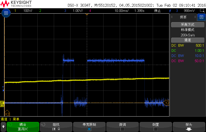
发现在最初的前几十个中断中读到的AD值是错误的,硬件的AD口用示波器看是没有异常的。
想请教下专家,这时候除了看AD这块的配置,还需要关注其他哪里?
谢谢