Part Number: TMS320F28388D
Other Parts Discussed in Thread: TMDSCNCD28388D
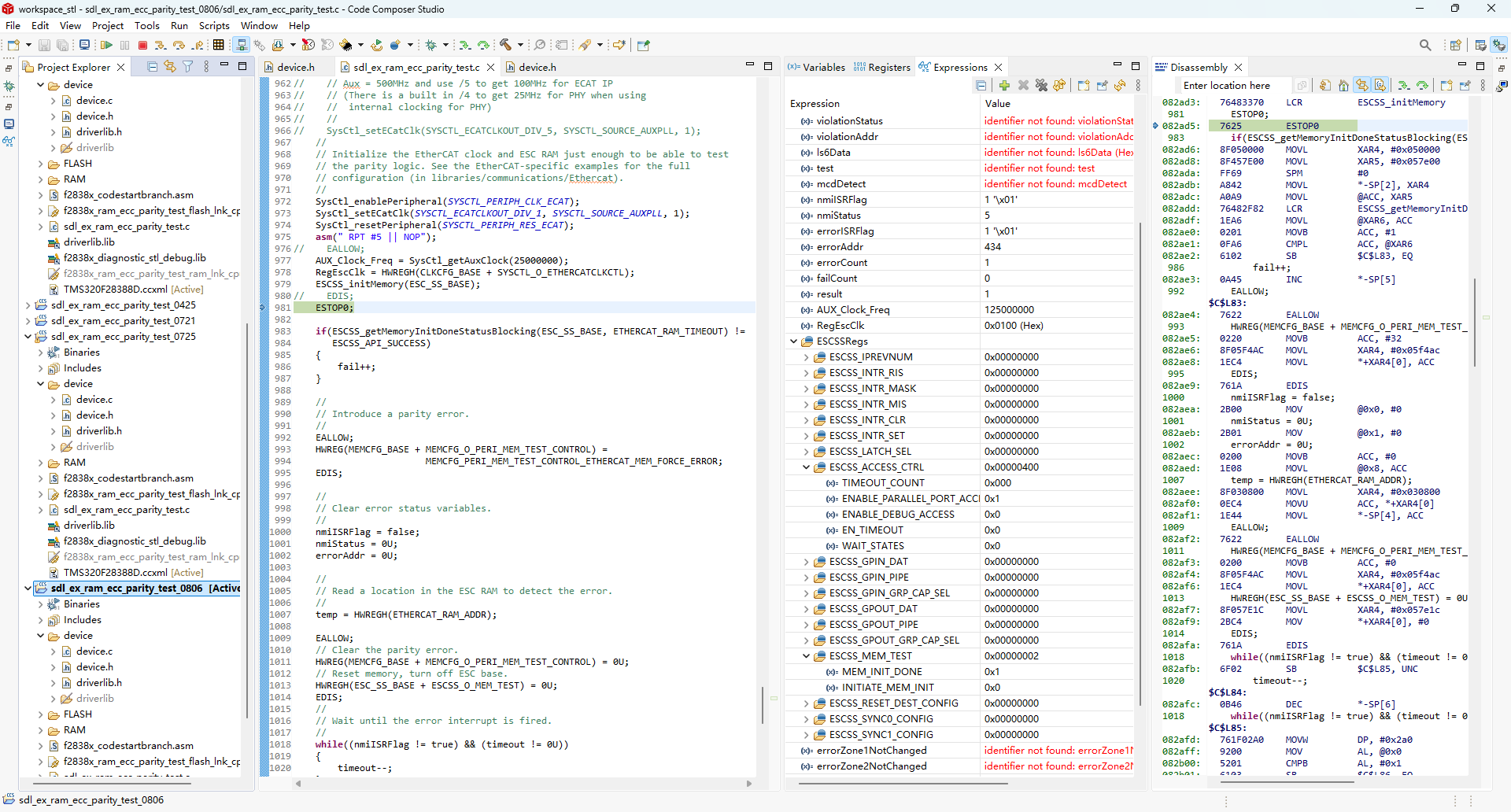
继上次的sdl_ex_ram_ecc_parity_test例程调试在10MHz晶振源的条件下测试失败的帖子(e2echina.ti.com/.../3639519
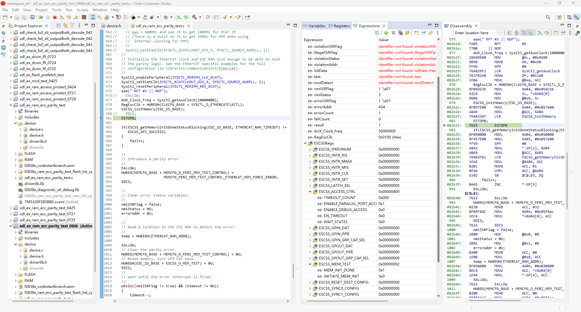
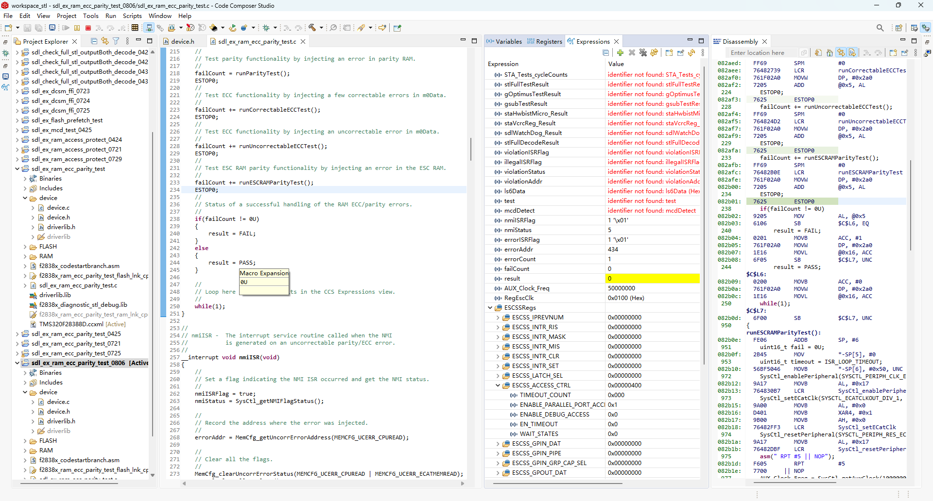
这是用TMDSCNCD28388D开发板(标准25MHz晶振源)运行此测试时的截图,可以看到ESCSS启动正常,且测试通过。
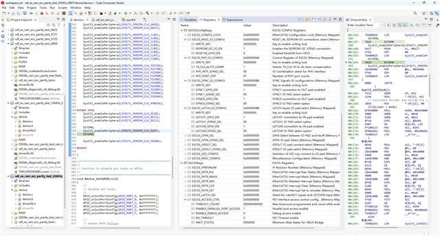
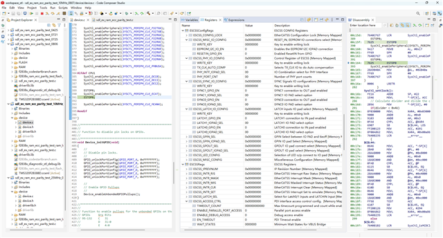
从25MHz源的工程到10MHz源的工程软件方面仅修改了device.h文件中的时钟链参数配置部分,如下所示。
原例程从25MHz源配置时钟链参数部分如下:
// USE_25MHZ_XTAL

//
// 25MHz XTAL on controlCARD. For use with SysCtl_getClock() and
// SysCtl_getAuxClock().
//
#define DEVICE_OSCSRC_FREQ          25000000U

//
// Define to pass to SysCtl_setClock(). Will configure the clock as follows:
// PLLSYSCLK = 25MHz (XTAL_OSC) * 32 (IMULT) / (2 (REFDIV) * 2 (ODIV) * 1(SYSDIV))
//
#define DEVICE_SETCLOCK_CFG          (SYSCTL_OSCSRC_XTAL_SE | SYSCTL_IMULT(32) | \
                                      SYSCTL_REFDIV(2) | SYSCTL_ODIV(2) | \
                                      SYSCTL_SYSDIV(1) | SYSCTL_PLL_ENABLE | \
                                      SYSCTL_DCC_BASE_1)

//
// 200MHz SYSCLK frequency based on the above DEVICE_SETCLOCK_CFG. Update the
// code below if a different clock configuration is used!
//
#define DEVICE_SYSCLK_FREQ          ((DEVICE_OSCSRC_FREQ * 32) / (2 * 2 * 1))

//
// 50MHz LSPCLK frequency based on the above DEVICE_SYSCLK_FREQ and a default
// low speed peripheral clock divider of 4. Update the code below if a
// different LSPCLK divider is used!
//
#define DEVICE_LSPCLK_FREQ          (DEVICE_SYSCLK_FREQ / 4)

//
// Define to pass to SysCtl_setAuxClock(). Will configure the clock as follows:
// AUXPLLCLK = 25MHz (XTAL_OSC) * 40 (IMULT) / (2 (REFDIV) * 4 (ODIV) * 1(AUXPLLDIV) )
//
#define DEVICE_AUXSETCLOCK_CFG       (SYSCTL_AUXPLL_OSCSRC_XTAL | SYSCTL_AUXPLL_IMULT(40) |  \
                                      SYSCTL_REFDIV(2U) | SYSCTL_ODIV(4U) | \
                                      SYSCTL_AUXPLL_DIV_1 | SYSCTL_AUXPLL_ENABLE | \
                                      SYSCTL_DCC_BASE_0)

//
// 125MHz AUXCLK frequency based on the above DEVICE_AUXSETCLOCK_CFG. Update
// the code below if a different clock configuration is used!
//
#define DEVICE_AUXCLK_FREQ          ((DEVICE_OSCSRC_FREQ * 40) / (2 * 4 * 1))
改为从10MHz源出发后配置参数如下:// USE_10MHZ_XTAL
//
// 10MHz XTAL on eRob-Master. For use with SysCtl_getClock() and
// SysCtl_getAuxClock().
//
#define DEVICE_OSCSRC_FREQ 10000000U
//
// Define to pass to SysCtl_setClock(). Will configure the clock as follows:
// PLLSYSCLK = 10MHz (XTAL_OSC) * 80 (IMULT) / (2 (REFDIV) * 2 (ODIV) * 1(SYSDIV))
//
#define DEVICE_SETCLOCK_CFG (SYSCTL_OSCSRC_XTAL_SE | SYSCTL_IMULT(80) | \
SYSCTL_REFDIV(2) | SYSCTL_ODIV(2) | \
SYSCTL_SYSDIV(1) | SYSCTL_PLL_ENABLE | \
SYSCTL_DCC_BASE_1)
//
// 200MHz SYSCLK frequency based on the above DEVICE_SETCLOCK_CFG. Update the
// code below if a different clock configuration is used!
//
#define DEVICE_SYSCLK_FREQ ((DEVICE_OSCSRC_FREQ * 80) / (2 * 2 * 1))
//
// 50MHz LSPCLK frequency based on the above DEVICE_SYSCLK_FREQ and a default
// low speed peripheral clock divider of 4. Update the code below if a
// different LSPCLK divider is used!
//
#define DEVICE_LSPCLK_FREQ (DEVICE_SYSCLK_FREQ / 4)
//
// Define to pass to SysCtl_setAuxClock(). Will configure the clock as follows:
// AUXPLLCLK = 10MHz (XTAL_OSC) * 50 (IMULT) / (2 (REFDIV) * 2 (ODIV) * 1(AUXPLLDIV) )
//
#define DEVICE_AUXSETCLOCK_CFG (SYSCTL_AUXPLL_OSCSRC_XTAL | SYSCTL_AUXPLL_IMULT(50) | \
SYSCTL_REFDIV(2U) | SYSCTL_ODIV(2U) | \
SYSCTL_AUXPLL_DIV_1 | SYSCTL_AUXPLL_ENABLE | \
SYSCTL_DCC_BASE_0)
//
// 125MHz AUXCLK frequency based on the above DEVICE_AUXSETCLOCK_CFG. Update
// the code below if a different clock configuration is used!
//
#define DEVICE_AUXCLK_FREQ ((DEVICE_OSCSRC_FREQ * 50) / (2 * 2 * 1))
为什么在25MHz的开发板上ESCSS能启动正常,在10MHz的工程板上却不能正常启动。