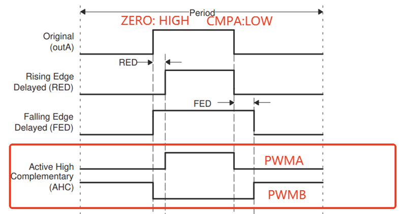
TMS320F2800137: 带死区的PWM,在duty为0时,为什么PWMB路输出一直为高电平

Part Number: TMS320F2800137

一组带死区功能的PWM,PWM原始信号输入选择A,设定ZERO:HIGH;CMPA:LOW

当CMPA =0是,示波器观察到PWMA输出一直为低电平(是想要的波形),PWMB输出一直为高电平(不是想要的波形,按我的理解应该是带死区的方波),请问为什么?
ca733cd2-6ae9-4d9c-876c-28846982c590.png

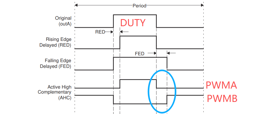
当duty=0时,蓝色圆框中的FED死区为什么不起作用,PWMB输出一直高电平。

  • 谢谢你的回复。

    这是按照这个完整的手册进行配置的TMS320F280013x Real-Time Microcontrollers Technical Reference Manual (Rev. B),在Duty不为0时,我的输出波形PWMA、PWMB都是正常的,问题只出现在duty=0时,我觉得这是一个特殊情况。

    你的链接我也看过了,文档里只展示了duty=36.8%的情况,并没有说明duty=0时会怎么样。希望你能验证一下duty=0时是否会出现PWMB一直高电平的问题。

  • 您好

    For this use-case, all three ePWM modules are set up for active high complementary signals. Meaning ePWMxA
    remains as is with a rising edge delay (RED) and ePWMB has the same source signal as ePWMA, but it is
    inverted with a falling edge delay (FED) instead of a rising edge delay. Figure 5-1 illustrates these two signals.
    In order to set up these signal pairs, utilize the deadband submodule as it allows you to apply this scheme of
    outputs along with many other signal pairs.
    To begin, take a look at the deadband submodule, which is essentially a set of switches that work together to
    achieve the desired output. S4 and S5 decide what the source signal is for the rest of the submodules: ePWMA
    or ePWMB. Since you want the same source signal for both resulting ePWMA and ePWMB outputs, set both
    switches to the ePWMA input. Next is S8, which is responsible for deciding which of the outputs will have RED
    and FED or both applied to it. Only one channel, either A or B, can have both RED and FED.

    在这部分说明为了能处理更多的信号而如此设计。这是对于这部分的说明