

您好,
我选择用的是SPLL_1ph_SOGI_IQ_H_,环路滤波器的PI参数按照TI太阳能库里给的excel文件计算得。
原SPLL_1ph_SOGI_IQ.h文件是IQ23格式,我改成了IQ18格式。这个是可以更改的吧。锁相有时候会锁住,有时在同样工况下就明显观察到角度差变大。
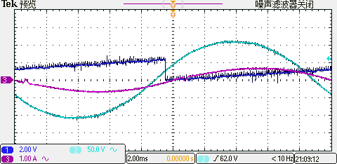
而且在取得相角的基础上,经过sin后乘以一个电流基准值,可从放大的波形中发现电网电压,相角,相角正弦值*电流,三者均不在同一相位上。请问这是什么问题?
程序和波形见下方。
 这是正常的时候
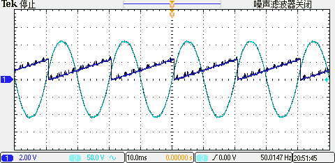
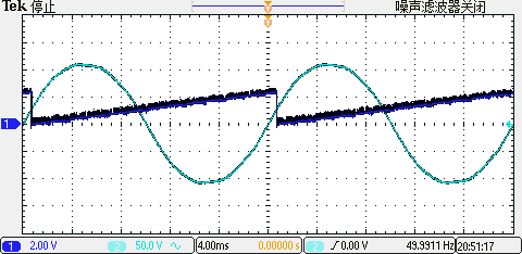 同样工况下有时候就明显观察到相角差变大
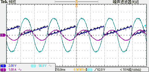
十分感谢您的回答。
您好,
我选择用的是SPLL_1ph_SOGI_IQ_H_,环路滤波器的PI参数按照TI太阳能库里给的excel文件计算得。
原SPLL_1ph_SOGI_IQ.h文件是IQ23格式,我改成了IQ18格式。这个是可以更改的吧。锁相有时候会锁住,有时在同样工况下就明显观察到角度差变大。
而且在取得相角的基础上,经过sin后乘以一个电流基准值,可从放大的波形中发现电网电压,相角,相角正弦值*电流,三者均不在同一相位上。请问这是什么问题?
程序和波形见下方。
十分感谢您的回答。

