

在使用例程lab27_adc_soc_epwm的时候,想把adca修改成ADCb,结果进不了中断了,跪求大家帮忙看看是哪里配置出了问题,感激不尽。下面是我的代码配置。


//###########################################################################
// FILE: adc_soc_epwm_cpu01.c
// TITLE: ADC triggering via epwm for F2837xS.
//
//! \addtogroup cpu01_example_list
//! <h1> ADC ePWM Triggering (adc_soc_epwm)</h1>
//!
//! This example sets up the ePWM to periodically trigger the ADC.
//!
//! After the program runs, the memory will contain:\n
//! - \b AdcaResults \b: A sequence of analog-to-digital conversion samples from
//! pin A0. The time between samples is determined based on the period
//! of the ePWM timer.
//
//###########################################################################
// $TI Release: F2837xS Support Library v190 $
// $Release Date: Mon Feb 1 16:59:09 CST 2016 $
// $Copyright: Copyright (C) 2014-2016 Texas Instruments Incorporated -
// http://www.ti.com/ ALL RIGHTS RESERVED $
//###########################################################################
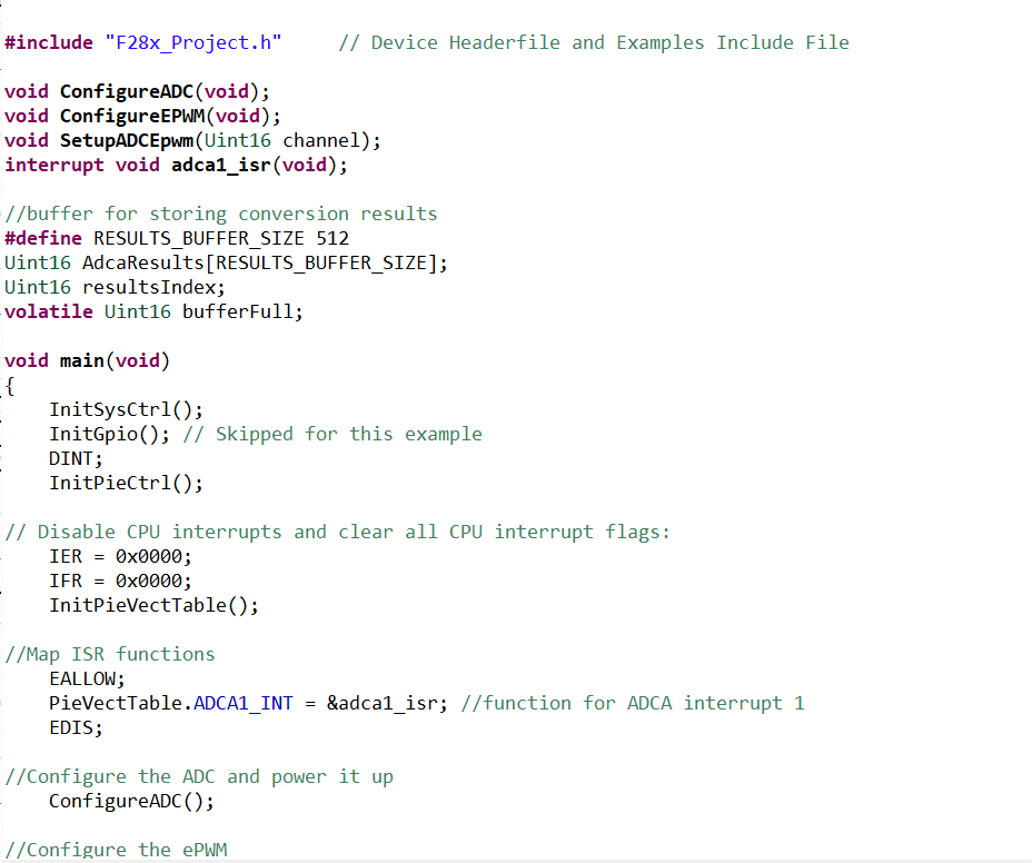
#include "F28x_Project.h" // Device Headerfile and Examples Include File
void ConfigureADC(void);
void ConfigureEPWM(void);
void SetupADCEpwm(Uint16 channel);
interrupt void adca1_isr(void);
//buffer for storing conversion results
#define RESULTS_BUFFER_SIZE 512
Uint16 AdcaResults[RESULTS_BUFFER_SIZE];
Uint16 resultsIndex;
volatile Uint16 bufferFull;
void main(void)
{
// Step 1. Initialize System Control:
// PLL, WatchDog, enable Peripheral Clocks
// This example function is found in the F2837xS_SysCtrl.c file.
InitSysCtrl();
// Step 2. Initialize GPIO:
// This example function is found in the F2837xS_Gpio.c file and
// illustrates how to set the GPIO to it's default state.
InitGpio(); // Skipped for this example
// Step 3. Clear all interrupts and initialize PIE vector table:
// Disable CPU interrupts
DINT;
// Initialize the PIE control registers to their default state.
// The default state is all PIE interrupts disabled and flags
// are cleared.
// This function is found in the F2837xS_PieCtrl.c file.
InitPieCtrl();
// Disable CPU interrupts and clear all CPU interrupt flags:
IER = 0x0000;
IFR = 0x0000;
// Initialize the PIE vector table with pointers to the shell Interrupt
// Service Routines (ISR).
// This will populate the entire table, even if the interrupt
// is not used in this example. This is useful for debug purposes.
// The shell ISR routines are found in F2837xS_DefaultIsr.c.
// This function is found in F2837xS_PieVect.c.
InitPieVectTable();
//Map ISR functions
EALLOW;
PieVectTable.ADCA1_INT = &adca1_isr; //function for ADCA interrupt 1
EDIS;
//Configure the ADC and power it up
ConfigureADC();
//Configure the ePWM
ConfigureEPWM();
//Setup the ADC for ePWM triggered conversions on channel 0
SetupADCEpwm(0);
//Enable global Interrupts and higher priority real-time debug events:
IER |= M_INT1; //Enable group 1 interrupts
EINT; // Enable Global interrupt INTM
ERTM; // Enable Global realtime interrupt DBGM
//Initialize results buffer
for(resultsIndex = 0; resultsIndex < RESULTS_BUFFER_SIZE; resultsIndex++)
{
AdcaResults[resultsIndex] = 0;
}
resultsIndex = 0;
bufferFull = 0;
//enable PIE interrupt
PieCtrlRegs.PIEIER1.bit.INTx1 = 1;
//sync ePWM
EALLOW;
CpuSysRegs.PCLKCR0.bit.TBCLKSYNC = 1;
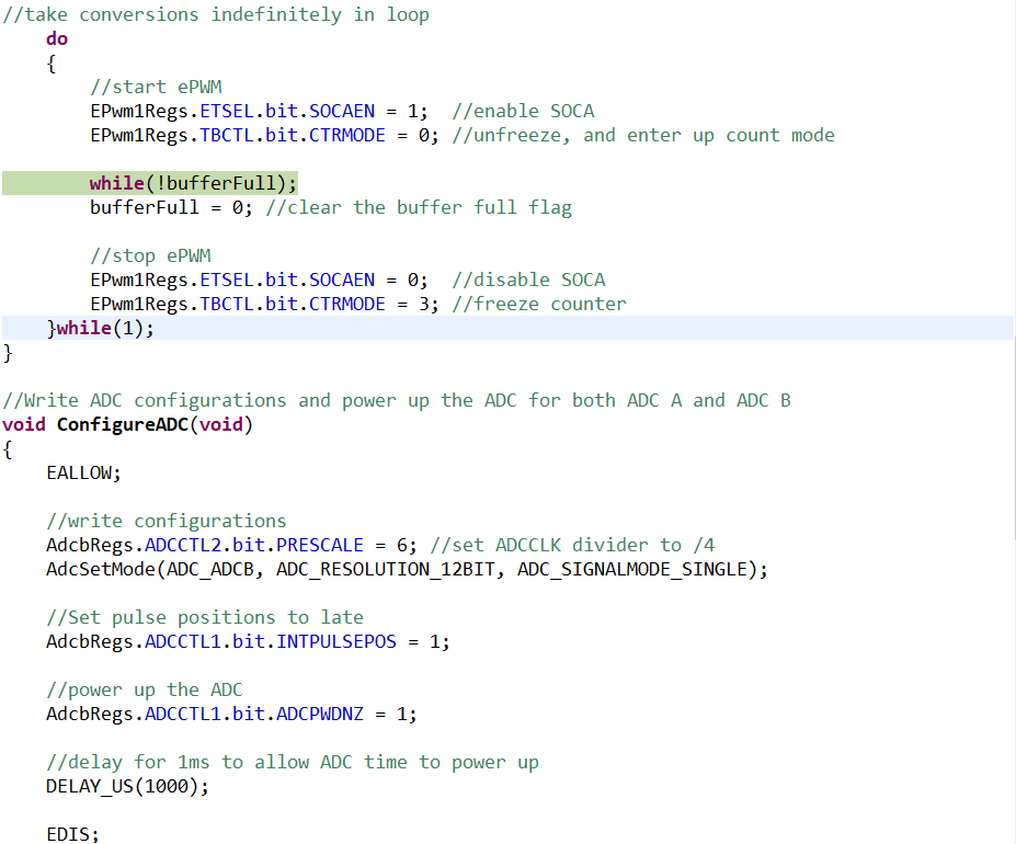
//take conversions indefinitely in loop
do
{
//start ePWM
EPwm1Regs.ETSEL.bit.SOCAEN = 1; //enable SOCA
EPwm1Regs.TBCTL.bit.CTRMODE = 0; //unfreeze, and enter up count mode
//wait while ePWM causes ADC conversions, which then cause interrupts,
//which fill the results buffer, eventually setting the bufferFull
//flag
while(!bufferFull);
bufferFull = 0; //clear the buffer full flag
//stop ePWM
EPwm1Regs.ETSEL.bit.SOCAEN = 0; //disable SOCA
EPwm1Regs.TBCTL.bit.CTRMODE = 3; //freeze counter
//at this point, AdcaResults[] contains a sequence of conversions
//from the selected channel
//software breakpoint, hit run again to get updated conversions
//asm(" ESTOP0");
}while(1);
}
//Write ADC configurations and power up the ADC for both ADC A and ADC B
void ConfigureADC(void)
{
EALLOW;
//write configurations
AdcbRegs.ADCCTL2.bit.PRESCALE = 6; //set ADCCLK divider to /4
AdcSetMode(ADC_ADCB, ADC_RESOLUTION_12BIT, ADC_SIGNALMODE_SINGLE);
//Set pulse positions to late
AdcbRegs.ADCCTL1.bit.INTPULSEPOS = 1;
//power up the ADC
AdcbRegs.ADCCTL1.bit.ADCPWDNZ = 1;
//delay for 1ms to allow ADC time to power up
DELAY_US(1000);
EDIS;
}
void ConfigureEPWM(void)
{
EALLOW;
// Assumes ePWM clock is already enabled
EPwm1Regs.ETSEL.bit.SOCAEN = 0; // Disable SOC on A group
EPwm1Regs.ETSEL.bit.SOCASEL = 6; // Select SOC on up-count
EPwm1Regs.ETPS.bit.SOCAPRD = 1; // Generate pulse on 1st event
EPwm1Regs.CMPA.bit.CMPA = 0x0800; // Set compare A value to 2048 counts
EPwm1Regs.TBPRD = 0x1000; // Set period to 4096 counts
EPwm1Regs.TBCTL.bit.CTRMODE = 3; // freeze counter
EDIS;
}
void SetupADCEpwm(Uint16 channel)
{
Uint16 acqps;
//determine minimum acquisition window (in SYSCLKS) based on resolution
if(ADC_RESOLUTION_12BIT == AdcbRegs.ADCCTL2.bit.RESOLUTION){
acqps = 14; //75ns
}
else { //resolution is 16-bit
acqps = 63; //320ns
}
//Select the channels to convert and end of conversion flag
EALLOW;
AdcbRegs.ADCSOC0CTL.bit.CHSEL = channel; //SOC0 will convert pin A0
AdcbRegs.ADCSOC0CTL.bit.ACQPS = acqps; //sample window is 100 SYSCLK cycles
AdcbRegs.ADCSOC0CTL.bit.TRIGSEL = 6; //trigger on ePWM1 SOCA/C
AdcbRegs.ADCINTSEL1N2.bit.INT1SEL = 0; //end of SOC0 will set INT1 flag
AdcbRegs.ADCINTSEL1N2.bit.INT1E = 1; //enable INT1 flag
AdcbRegs.ADCINTFLGCLR.bit.ADCINT1 = 1; //make sure INT1 flag is cleared
}
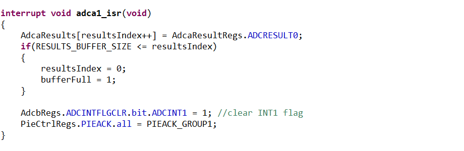
interrupt void adca1_isr(void)
{
AdcaResults[resultsIndex++] = AdcaResultRegs.ADCRESULT0;
if(RESULTS_BUFFER_SIZE <= resultsIndex)
{
resultsIndex = 0;
bufferFull = 1;
}
AdcbRegs.ADCINTFLGCLR.bit.ADCINT1 = 1; //clear INT1 flag
PieCtrlRegs.PIEACK.all = PIEACK_GROUP1;
}

