If you have a related question, please click the "Ask a related question" button in the top right corner. The newly created question will be automatically linked to this question.
// TI File $Revision: /main/3 $
// Checkin $Date: July 2, 2007 11:33:46 $
//###########################################################################
//
// FILE: Example_281xAdc.c
//
// TITLE: DSP281x ADC Example Program.
//
// ASSUMPTIONS:
//
// This program requires the DSP281x V1.00 header files.
// As supplied, this project is configured for "boot to H0" operation.
//
// Make sure the CPU clock speed is properly defined in
// DSP281x_Examples.h before compiling this example.
//
// Connect signals to be converted to A2 and A3.
//
//
// DESCRIPTION:
//
// This example sets up the PLL in x10/2 mode, divides SYSCLKOUT
// by six to reach a 25Mhz HSPCLK (assuming a 30Mhz XCLKIN). The
// clock divider in the ADC is not used so that the ADC will see
// the 25Mhz on the HSPCLK. Interrupts are enabled and the EVA
// is setup to generate a periodic ADC SOC on SEQ1. Two channels
// are converted, ADCINA3 and ADCINA2.
//
// Watch Variables:
//
// Voltage1[10] Last 10 ADCRESULT0 values
// Voltage2[10] Last 10 ADCRESULT1 values
// ConversionCount Current result number 0-9
// LoopCount Idle loop counter
//
//
//###########################################################################
// $TI Release: DSP281x C/C++ Header Files V1.20 $
// $Release Date: July 27, 2009 $
//###########################################################################
#include "DSP281x_Device.h" // DSP281x Headerfile Include File
#include "DSP281x_Examples.h" // DSP281x Examples Include File
// Prototype statements for functions found within this file.
interrupt void adc_isr(void);
interrupt void cpu_timer0_isr(void);
// Global variables used in this example:
Uint16 LoopCount;
Uint16 ConversionCount;
Uint16 Voltage1[10];
Uint16 Voltage2[10];
main()
{
// Step 1. Initialize System Control:
// PLL, WatchDog, enable Peripheral Clocks
// This example function is found in the DSP281x_SysCtrl.c file.
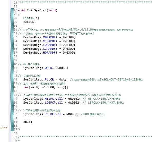
InitSysCtrl();
// For this example, set HSPCLK to SYSCLKOUT / 6 (25Mhz assuming 150Mhz SYSCLKOUT)
EALLOW;
SysCtrlRegs.HISPCP.all = 0x3; // HSPCLK = SYSCLKOUT/6
EDIS;
// Step 2. Initialize GPIO:
// This example function is found in the DSP281x_Gpio.c file and
// illustrates how to set the GPIO to it's default state.
// InitGpio(); // Skipped for this example
// Step 3. Clear all interrupts and initialize PIE vector table:
// Disable CPU interrupts
DINT;
// Initialize the PIE control registers to their default state.
// The default state is all PIE interrupts disabled and flags
// are cleared.
// This function is found in the DSP281x_PieCtrl.c file.
InitPieCtrl();
// Disable CPU interrupts and clear all CPU interrupt flags:
IER = 0x0000;
IFR = 0x0000;
// Initialize the PIE vector table with pointers to the shell Interrupt
// Service Routines (ISR).
// This will populate the entire table, even if the interrupt
// is not used in this example. This is useful for debug purposes.
// The shell ISR routines are found in DSP281x_DefaultIsr.c.
// This function is found in DSP281x_PieVect.c.
InitPieVectTable();
// Interrupts that are used in this example are re-mapped to
// ISR functions found within this file.
EALLOW; // This is needed to write to EALLOW protected register
PieVectTable.ADCINT = &adc_isr;
PieVectTable.TINT0 = &cpu_timer0_isr;
// This is needed to disable write to EALLOW protected registers
GpioMuxRegs.GPAMUX.bit.PWM1_GPIOA0=0;
GpioMuxRegs.GPADIR.bit.GPIOA0=1;
EDIS;
// Step 4. Initialize all the Device Peripherals:
// This function is found in DSP281x_InitPeripherals.c
// InitPeripherals(); // Not required for this example
InitCpuTimers(); // For this example, only initialize the Cpu Timers
// Configure CPU-Timer 0 to interrupt every second:
// 150MHz CPU Freq, 1 second Period (in uSeconds)
ConfigCpuTimer(&CpuTimer0, 150, 1000000);
// Step 4. Initialize all the Device Peripherals:
// This function is found in DSP281x_InitPeripherals.c
// InitPeripherals(); // Not required for this example
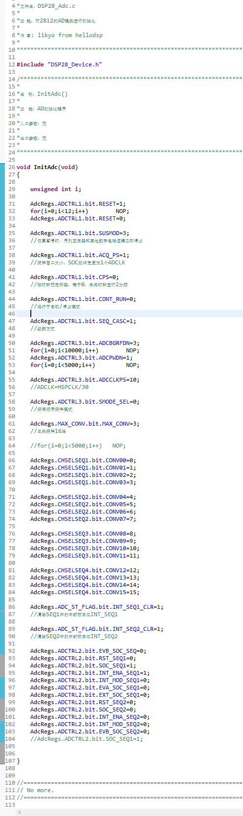
InitAdc(); // For this example, init the ADC
// Step 5. User specific code, enable interrupts:
// Enable ADCINT in PIE
PieCtrlRegs.PIEIER1.bit.INTx6 = 1;
PieCtrlRegs.PIEIER1.bit.INTx7 = 1;
IER |= M_INT1; // Enable CPU Interrupt 1
EINT; // Enable Global interrupt INTM
ERTM; // Enable Global realtime interrupt DBGM
LoopCount = 0;
ConversionCount = 0;
// Configure ADC
AdcRegs.ADCMAXCONV.all = 0x0001; // Setup 2 conv's on SEQ1
AdcRegs.ADCCHSELSEQ1.bit.CONV00 = 0x0; // Setup ADCINA3 as 1st SEQ1 conv.
AdcRegs.ADCCHSELSEQ1.bit.CONV01 = 0x0; // Setup ADCINA2 as 2nd SEQ1 conv.
AdcRegs.ADCTRL2.bit.INT_ENA_SEQ1 = 1; // Enable SEQ1 interrupt (every EOS)
StartCpuTimer0();
// Wait for ADC interrupt
while(1)
{
LoopCount++;
}
}
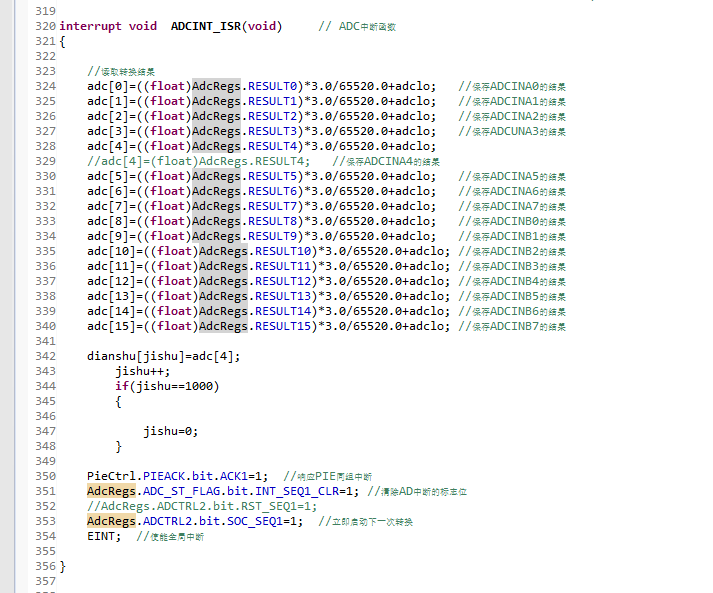
interrupt void adc_isr(void)
{
GpioDataRegs.GPATOGGLE.bit.GPIOA0=1;
Voltage1[ConversionCount] = AdcRegs.ADCRESULT0 >>4;
Voltage2[ConversionCount] = AdcRegs.ADCRESULT1 >>4;
// If 40 conversions have been logged, start over
if(ConversionCount == 9)
{
ConversionCount = 0;
}
else ConversionCount++;
// Reinitialize for next ADC sequence
AdcRegs.ADCTRL2.bit.RST_SEQ1 = 1; // Reset SEQ1
AdcRegs.ADCST.bit.INT_SEQ1_CLR = 1; // Clear INT SEQ1 bit
PieCtrlRegs.PIEACK.all = PIEACK_GROUP1; // Acknowledge interrupt to PIE
return;
}
interrupt void cpu_timer0_isr(void)
{
while(AdcRegs.ADCST.bit.SEQ1_BSY==0) //�˴�����ADת��ģʽ
{
AdcRegs.ADCTRL2.bit.SOC_SEQ1=1;
}
CpuTimer0.InterruptCount++;
// Acknowledge this interrupt to receive more interrupts from group 1
PieCtrlRegs.PIEACK.all = PIEACK_GROUP1;
}