This thread has been locked.

If you have a related question, please click the "Ask a related question" button in the top right corner. The newly created question will be automatically linked to this question.

28377S,CAN通讯

Other Parts Discussed in Thread: CONTROLSUITE

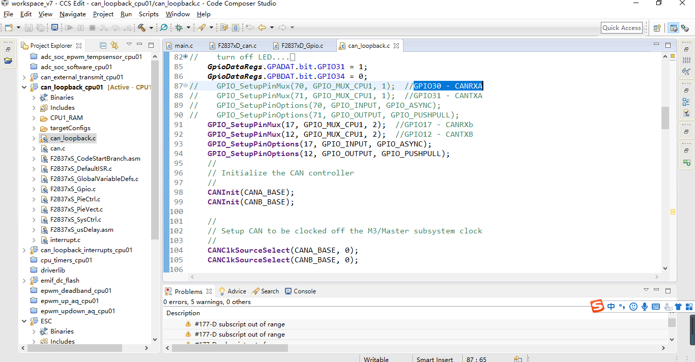
我使用的例程是controlSUITE\device_support\F2837xS\v210\F2837xS_examples_Cpu1\can_loopback\cpu01\ccs

GPIO70 - CANRXA,GPIO71 - CANTXA

下载28377S板子(这个板子是自己设计开发,已经验证电路正常)后can无法通讯,

同一个例程,GPIO17 - CANRXA,GPIO12 - CANTXA,下载到28379DLaunchPad,可以通讯

是不是这个例程用70,71引脚不兼容,还有其他适用于28377S的CAN例程吗,引脚已经不能修改了。

还有其他地方需要修改吗,如图就是我修改的地方

  • 请您看一下数据手册的

    Table 4-1. Signal Descriptions

    www.ti.com/.../tms320f28377s.pdf

    在手册中描述: GPIO70 - CANRXA,GPIO71 - CANTXA

    而 GPIO17 GPIO12 的CANRXB/CANTXB

    您还需要修改CANA_BASE为CANB_BASE

    另外在controlSUITE\device_support\F2837xS\v210\F2837xS_examples_Cpu1\can_loopback\cpu01\ccs使用的是

    GPIO_SetupPinMux(30, GPIO_MUX_CPU1, 1); //GPIO30 - CANRXA
    GPIO_SetupPinMux(31, GPIO_MUX_CPU1, 1); //GPIO31 - CANTXA
  • CANA_BASE为CANB_BASE,我注意到了,已经修改过后测试,CAN通讯不上。
  • 我看您给出的截图内CANA的没有注释掉

    能否使用右下角高级编辑器贴一下完整的代码吗?
  • /*
    * main.c
    *
    * Created on: 2021年1月8日
    * Author: KXH
    */


    //###########################################################################
    //
    // FILE: can_loopback.c
    //
    // TITLE: Example to demonstrate basic CAN setup and use.
    //
    //! \addtogroup cpu01_example_list
    //! <h1>CAN External Loopback Using Driverlib (can_loopback)</h1>
    //!
    //! This example, using driverlib, shows the basic setup of CAN in order to
    //! transmit and receive messages on the CAN bus. The CAN peripheral is
    //! configured to transmit messages with a specific CAN ID. A message is then
    //! transmitted once per second, using a simple delay loop for timing. The
    //! message that is sent is a 4 byte message that contains an incrementing
    //! pattern. A CAN interrupt handler is used to confirm message transmission
    //! and count the number of messages that have been sent.
    //!
    //! This example sets up the CAN controller in External Loopback test mode.
    //! Data transmitted is visible on the CAN0TX pin and can be received with
    //! an appropriate mailbox configuration.
    //!
    //
    //###########################################################################
    // $TI Release: F2837xS Support Library v210 $
    // $Release Date: Tue Nov 1 15:35:23 CDT 2016 $
    // $Copyright: Copyright (C) 2014-2016 Texas Instruments Incorporated -
    // http://www.ti.com/ ALL RIGHTS RESERVED $
    //###########################################################################

    //
    // Included Files
    //
    #include "F28x_Project.h"
    #include <stdint.h>
    #include <stdbool.h>
    #include "inc/hw_types.h"
    #include "inc/hw_memmap.h"
    #include "inc/hw_can.h"
    #include "driverlib/can.h"

    //
    // Globals
    //
    volatile unsigned long g_ulMsgCount = 0; // A counter that keeps track of the
    // number of times the transmit was
    // successful.
    volatile unsigned long g_bErrFlag = 0; // A flag to indicate that some
    // transmission error occurred.

    //
    // Main
    //
    int
    main(void)
    {
    tCANMsgObject sTXCANMessage;
    tCANMsgObject sRXCANMessage;
    unsigned char ucTXMsgData[8], ucRXMsgData[8];
    int i=0;
    uint16_t time = 0;

    //
    // Step 1. Initialize System Control:
    // PLL, WatchDog, enable Peripheral Clocks
    // This example function is found in the F2837xS_SysCtrl.c file.
    //
    InitSysCtrl();

    //
    // Step 2. Initialize GPIO:
    // This example function is found in the F2837xS_Gpio.c file and
    // illustrates how to set the GPIO to its default state.
    //
    InitGpio();
    EALLOW;
    //1、端口初始化
    //2、端口方向
    GpioCtrlRegs.GPADIR.bit.GPIO31 = 1;
    GpioCtrlRegs.GPBDIR.bit.GPIO34 = 1;
    EDIS;

    // turn off LED....
    // LED1 = OFF;//blue
    // LED2 = ON;//red
    GpioDataRegs.GPADAT.bit.GPIO31 = 1;
    GpioDataRegs.GPBDAT.bit.GPIO34 = 0;
    GPIO_SetupPinMux(70, GPIO_MUX_CPU1, 1); //GPIO30 - CANRXA
    GPIO_SetupPinMux(71, GPIO_MUX_CPU1, 1); //GPIO31 - CANTXA
    GPIO_SetupPinOptions(70, GPIO_INPUT, GPIO_ASYNC);
    GPIO_SetupPinOptions(71, GPIO_OUTPUT, GPIO_PUSHPULL);
    // GPIO_SetupPinMux(17, GPIO_MUX_CPU1, 2); //GPIO17 - CANRXb
    // GPIO_SetupPinMux(12, GPIO_MUX_CPU1, 2); //GPIO12 - CANTXB
    // GPIO_SetupPinOptions(17, GPIO_INPUT, GPIO_ASYNC);
    // GPIO_SetupPinOptions(12, GPIO_OUTPUT, GPIO_PUSHPULL);
    //
    // Initialize the CAN controller
    //
    CANInit(CANA_BASE);
    // CANInit(CANB_BASE);

    //
    // Setup CAN to be clocked off the M3/Master subsystem clock
    //
    CANClkSourceSelect(CANA_BASE, 0);
    // CANClkSourceSelect(CANB_BASE, 0);

    //
    // Set up the bit rate for the CAN bus. This function sets up the CAN
    // bus timing for a nominal configuration. You can achieve more control
    // over the CAN bus timing by using the function CANBitTimingSet() instead
    // of this one, if needed.
    // In this example, the CAN bus is set to 500 kHz. In the function below,
    // the call to SysCtlClockGet() is used to determine the clock rate that0
    // is used for clocking the CAN peripheral. This can be replaced with a
    // fixed value if you know the value of the system clock, saving the extra
    // function call. For some parts, the CAN peripheral is clocked by a fixed
    // 8 MHz regardless of the system clock in which case the call to
    // SysCtlClockGet() should be replaced with 8000000. Consult the data
    // sheet for more information about CAN peripheral clocking.
    //
    CANBitRateSet(CANA_BASE, 200000000, 1000000);
    // CANBitRateSet(CANB_BASE, 200000000, 1000000);

    //
    // Step 3. Clear all interrupts and initialize PIE vector table:
    // Disable CPU interrupts
    //
    DINT;

    //
    // Initialize the PIE control registers to their default state.
    // The default state is all PIE interrupts disabled and flags
    // are cleared.
    // This function is found in the F2837xS_PieCtrl.c file.
    //
    InitPieCtrl();

    //
    // Disable CPU interrupts and clear all CPU interrupt flags:
    //
    IER = 0x0000;
    IFR = 0x0000;

    //
    // Initialize the PIE vector table with pointers to the shell Interrupt
    // Service Routines (ISR).
    // This will populate the entire table, even if the interrupt
    // is not used in this example. This is useful for debug purposes.
    // The shell ISR routines are found in F2837xS_DefaultIsr.c.
    // This function is found in F2837xS_PieVect.c.
    //
    InitPieVectTable();

    //
    // Enable test mode and select external loopback
    //
    // HWREG(CANA_BASE + CAN_O_CTL) |= CAN_CTL_TEST;
    // HWREG(CANA_BASE + CAN_O_TEST) = CAN_TEST_EXL;

    //
    // Enable the CAN for operation.
    //
    CANEnable(CANA_BASE);
    // CANEnable(CANB_BASE);

    //
    // Initialize the message object that will be used for sending CAN
    // messages. The message will be 4 bytes that will contain an incrementing
    // value. Initially it will be set to 0.
    //
    *(unsigned long *)ucTXMsgData = 0;
    sTXCANMessage.ui32MsgID = 1; // CAN message ID - use 1
    sTXCANMessage.ui32MsgIDMask = 0; // no mask needed for TX
    sTXCANMessage.ui32Flags = MSG_OBJ_TX_INT_ENABLE; // enable interrupt on TX
    sTXCANMessage.ui32MsgLen = sizeof(ucTXMsgData); // size of message is 4
    sTXCANMessage.pucMsgData = ucTXMsgData; // ptr to message content

    //
    // Initialize the message object that will be used for receiving CAN
    // messages.
    //
    *(unsigned long *)ucRXMsgData = 0;
    sRXCANMessage.ui32MsgID = 1; // CAN message ID - use 1
    sRXCANMessage.ui32MsgIDMask = 0; // no mask needed for TX
    sRXCANMessage.ui32Flags = MSG_OBJ_NO_FLAGS;
    sRXCANMessage.ui32MsgLen = sizeof(ucRXMsgData); // size of message is 4
    sRXCANMessage.pucMsgData = ucRXMsgData; // ptr to message content

    //
    // Setup the message object being used to receive messages
    //
    CANMessageSet(CANA_BASE, 2, &sRXCANMessage, MSG_OBJ_TYPE_RX);
    // CANMessageSet(CANB_BASE, 2, &sRXCANMessage, MSG_OBJ_TYPE_RX);
    //
    // Enter loop to send messages. A new message will be sent once per
    // second. The 4 bytes of message content will be treated as an unsigned
    // long and incremented by one each time.
    //
    for(;;)
    {
    //
    // Send the CAN message using object number 1 (not the same thing as
    // CAN ID, which is also 1 in this example). This function will cause
    // the message to be transmitted right away.
    //

    time=time++;
    GpioDataRegs.GPATOGGLE.bit.GPIO31=1;
    GpioDataRegs.GPBTOGGLE.bit.GPIO34=1;
    ucTXMsgData[0]=01;
    ucTXMsgData[1]=01;
    ucTXMsgData[2]=01;
    ucTXMsgData[3]=01;
    ucTXMsgData[4]=01;
    ucTXMsgData[5]=01;
    ucTXMsgData[6]=01;
    ucTXMsgData[7]=01;

    CANMessageSet(CANA_BASE, 1, &sTXCANMessage, MSG_OBJ_TYPE_TX);
    // CANMessageSet(CANB_BASE, 1, &sTXCANMessage, MSG_OBJ_TYPE_TX);

    //
    // Now wait 1 second before continuing
    //
    DELAY_US(1000*100);

    //
    // Get the receive message
    //
    CANMessageGet(CANA_BASE, 2, &sRXCANMessage, true);
    // CANMessageGet(CANB_BASE, 2, &sRXCANMessage, true);

    //
    // Ensure the received data matches the transmitted data
    //
    // if((*(unsigned long *)ucTXMsgData) != (*(unsigned long *)ucRXMsgData))
    // {
    // asm(" ESTOP0");
    // }

    //
    // Increment the value in the transmitted message data.
    //
    // (*(unsigned long *)ucTXMsgData)++;
    }
    }

    //
    // End of file
    //

  • 请您之后使用右下角的“使用高级编辑器编辑文本”上传代码。

    关于GPIO修改,请参考文档