This thread has been locked.
If you have a related question, please click the "Ask a related question" button in the top right corner. The newly created question will be automatically linked to this question.
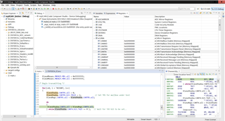
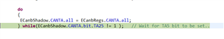
使用官方的示例程序(ecan_a_to_b_xmit)修改can通信 程序仿真会在如图所示的位置死循环 can的中断标志无法置位
修改后程序代码如下:
//########################################################################### // Description //! \addtogroup f2833x_example_list //! <h1>eCAN-A to eCAN-B Trasmit Loop (ecan_a_to_b_xmit)</h1> //! //! This example TRANSMITS data to another CAN module using MAILBOX5 //! This program could either loop forever or transmit "n" # of times, //! where "n" is the TXCOUNT value. \n //! //! This example can be used to check CAN-A and CAN-B. Since CAN-B is //! initialized in DSP2833x_ECan.c, it will acknowledge all frames //! transmitted by the node on which this code runs. Both CAN ports of //! the 2833x DSP need to be connected to each other (via CAN transceivers) //! //! \b External \b Connections \n //! - ECanb is on GPIO31 (CANTXA) and GPIO30 (CANRXA) //! - eCANB is on GPIO8 (CANTXB) and GPIO10 (CANRXB) //! - Connect ECanb to eCANB via CAN transceivers // //########################################################################### // $TI Release: F2833x/F2823x Header Files and Peripheral Examples V142 $ // $Release Date: November 1, 2016 $ // $Copyright: Copyright (C) 2007-2016 Texas Instruments Incorporated - // http://www.ti.com/ ALL RIGHTS RESERVED $ //########################################################################### #include "DSP2833x_Device.h" // DSP2833x Headerfile Include File #include "DSP2833x_Examples.h" // DSP2833x Examples Include File #define TXCOUNT 100 // Transmission will take place (TXCOUNT) times.. // Globals for this example long i; long loopcount = 0; void main() { // Create a shadow register structure for the CAN control registers. This is // needed, since only 32-bit access is allowed to these registers. 16-bit access // to these registers could potentially corrupt the register contents or return // false data. struct ECAN_REGS ECanbShadow; // Step 1. Initialize System Control: // PLL, WatchDog, enable Peripheral Clocks // This example function is found in the DSP2833x_SysCtrl.c file. InitSysCtrl(); // Step 2. Initialize GPIO: // This example function is found in the DSP2833x_Gpio.c file and // illustrates how to set the GPIO to it's default state. // InitGpio(); // Skipped for this example // Just initialize eCAN pins for this example // This function is in DSP2833x_ECan.c InitECanGpio(); // Step 3. Clear all interrupts and initialize PIE vector table: // Disable CPU interrupts DINT; // Initialize the PIE control registers to their default state. // The default state is all PIE interrupts disabled and flags // are cleared. // This function is found in the DSP2833x_PieCtrl.c file. InitPieCtrl(); // Disable CPU interrupts and clear all CPU interrupt flags: IER = 0x0000; IFR = 0x0000; // Initialize the PIE vector table with pointers to the shell Interrupt // Service Routines (ISR). // This will populate the entire table, even if the interrupt // is not used in this example. This is useful for debug purposes. // The shell ISR routines are found in DSP2833x_DefaultIsr.c. // This function is found in DSP2833x_PieVect.c. InitPieVectTable(); // Interrupts that are used in this example are re-mapped to // ISR functions found within this file. // No interrupts used in this example. // Step 4. Initialize all the Device Peripherals: // This function is found in DSP2833x_InitPeripherals.c // InitPeripherals(); // Not required for this example // In this case just initialize eCAN-A and eCAN-B // This function is in DSP2833x_ECan.c InitECan(); // Step 5. User specific code: /* Write to the MSGID field */ ECanbMboxes.MBOX25.MSGID.all = 0x95555555; // Extended Identifier /* Configure Mailbox under test as a Transmit mailbox */ ECanbShadow.CANMD.all = ECanbRegs.CANMD.all; ECanbShadow.CANMD.bit.MD25 = 0; ECanbRegs.CANMD.all = ECanbShadow.CANMD.all; /* Enable Mailbox under test */ ECanbShadow.CANME.all = ECanbRegs.CANME.all; ECanbShadow.CANME.bit.ME25 = 1; ECanbRegs.CANME.all = ECanbShadow.CANME.all; /* Write to DLC field in Master Control reg */ ECanbMboxes.MBOX25.MSGCTRL.bit.DLC = 8; /* Write to the mailbox RAM field */ ECanbMboxes.MBOX25.MDL.all = 0x01234567; ECanbMboxes.MBOX25.MDH.all = 0x89ABCDEF; /* Begin transmitting */ for(i=0; i < TXCOUNT; i++) { ECanbShadow.CANTRS.all = 0; ECanbShadow.CANTRS.bit.TRS25 = 1; // Set TRS for mailbox under test ECanbRegs.CANTRS.all = ECanbShadow.CANTRS.all; do { ECanbShadow.CANTA.all = ECanbRegs.CANTA.all; } while(ECanbShadow.CANTA.bit.TA25 != 1 ); // Wait for TA5 bit to be set.. ECanbShadow.CANTA.all = 0; ECanbShadow.CANTA.bit.TA25 = 1; // Clear TA5 ECanbRegs.CANTA.all = ECanbShadow.CANTA.all; loopcount ++; } __asm(" ESTOP0"); // Stop here }
你好 感谢回复 官方的例程仿真同样会卡在这个位置 CANTA无法置一
官方例程代码:
//########################################################################### // Description //! \addtogroup f2833x_example_list //! <h1>eCAN-A to eCAN-B Trasmit Loop (ecan_a_to_b_xmit)</h1> //! //! This example TRANSMITS data to another CAN module using MAILBOX5 //! This program could either loop forever or transmit "n" # of times, //! where "n" is the TXCOUNT value. \n //! //! This example can be used to check CAN-A and CAN-B. Since CAN-B is //! initialized in DSP2833x_ECan.c, it will acknowledge all frames //! transmitted by the node on which this code runs. Both CAN ports of //! the 2833x DSP need to be connected to each other (via CAN transceivers) //! //! \b External \b Connections \n //! - eCANA is on GPIO31 (CANTXA) and GPIO30 (CANRXA) //! - eCANB is on GPIO8 (CANTXB) and GPIO10 (CANRXB) //! - Connect eCANA to eCANB via CAN transceivers // //########################################################################### // $TI Release: F2833x/F2823x Header Files and Peripheral Examples V142 $ // $Release Date: November 1, 2016 $ // $Copyright: Copyright (C) 2007-2016 Texas Instruments Incorporated - // http://www.ti.com/ ALL RIGHTS RESERVED $ //########################################################################### #include "DSP2833x_Device.h" // DSP28 Headerfile Include File #include "DSP2833x_Examples.h" // DSP28 Examples Include File #define TXCOUNT 100 // Transmission will take place (TXCOUNT) times.. // Globals for this example long i; long loopcount = 0; void main() { // Create a shadow register structure for the CAN control registers. This is // needed, since only 32-bit access is allowed to these registers. 16-bit access // to these registers could potentially corrupt the register contents or return // false data. struct ECAN_REGS ECanaShadow; // Step 1. Initialize System Control: // PLL, WatchDog, enable Peripheral Clocks // This example function is found in the DSP2833x_SysCtrl.c file. InitSysCtrl(); // Step 2. Initialize GPIO: // This example function is found in the DSP2833x_Gpio.c file and // illustrates how to set the GPIO to it's default state. // InitGpio(); // Skipped for this example // Just initialize eCAN pins for this example // This function is in DSP2833x_ECan.c InitECanGpio(); // Step 3. Clear all interrupts and initialize PIE vector table: // Disable CPU interrupts DINT; // Initialize the PIE control registers to their default state. // The default state is all PIE interrupts disabled and flags // are cleared. // This function is found in the DSP2833x_PieCtrl.c file. InitPieCtrl(); // Disable CPU interrupts and clear all CPU interrupt flags: IER = 0x0000; IFR = 0x0000; // Initialize the PIE vector table with pointers to the shell Interrupt // Service Routines (ISR). // This will populate the entire table, even if the interrupt // is not used in this example. This is useful for debug purposes. // The shell ISR routines are found in DSP2833x_DefaultIsr.c. // This function is found in DSP2833x_PieVect.c. InitPieVectTable(); // Interrupts that are used in this example are re-mapped to // ISR functions found within this file. // No interrupts used in this example. // Step 4. Initialize all the Device Peripherals: // This function is found in DSP2833x_InitPeripherals.c // InitPeripherals(); // Not required for this example // In this case just initialize eCAN-A and eCAN-B // This function is in DSP2833x_ECan.c InitECan(); // Step 5. User specific code: /* Write to the MSGID field */ ECanaMboxes.MBOX25.MSGID.all = 0x95555555; // Extended Identifier /* Configure Mailbox under test as a Transmit mailbox */ ECanaShadow.CANMD.all = ECanaRegs.CANMD.all; ECanaShadow.CANMD.bit.MD25 = 0; ECanaRegs.CANMD.all = ECanaShadow.CANMD.all; /* Enable Mailbox under test */ ECanaShadow.CANME.all = ECanaRegs.CANME.all; ECanaShadow.CANME.bit.ME25 = 1; ECanaRegs.CANME.all = ECanaShadow.CANME.all; /* Write to DLC field in Master Control reg */ ECanaMboxes.MBOX25.MSGCTRL.bit.DLC = 8; /* Write to the mailbox RAM field */ ECanaMboxes.MBOX25.MDL.all = 0x55555555; ECanaMboxes.MBOX25.MDH.all = 0x55555555; /* Begin transmitting */ for(i=0; i < TXCOUNT; i++) { ECanaShadow.CANTRS.all = 0; ECanaShadow.CANTRS.bit.TRS25 = 1; // Set TRS for mailbox under test ECanaRegs.CANTRS.all = ECanaShadow.CANTRS.all; do { ECanaShadow.CANTA.all = ECanaRegs.CANTA.all; } while(ECanaShadow.CANTA.bit.TA25 == 0 ); // Wait for TA5 bit to be set.. ECanaShadow.CANTA.all = 0; ECanaShadow.CANTA.bit.TA25 = 1; // Clear TA5 ECanaRegs.CANTA.all = ECanaShadow.CANTA.all; loopcount ++; } __asm(" ESTOP0"); // Stop here }
抱歉,你上传的自己代码可能是选择的TXT格式的,所以看起来实在有点累。
就例程而言,卡在这个位置的话说明传输不成功,不知道你这边的硬件上有没有根据例程中提示的进行连接?即通过CAN收发器连接CANA和CANB
//! \b External \b Connections \n
//! - eCANA is on GPIO31 (CANTXA) and GPIO30 (CANRXA)
//! - eCANB is on GPIO8 (CANTXB) and GPIO10 (CANRXB)
//! - Connect eCANA to eCANB via CAN transceivers