This thread has been locked.

If you have a related question, please click the "Ask a related question" button in the top right corner. The newly created question will be automatically linked to this question.

TMS320F280023: 请问使用高精度PWM对PWM开关频率有最低要求吗?

Part Number: TMS320F280023
Other Parts Discussed in Thread: C2000WARE

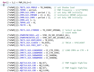
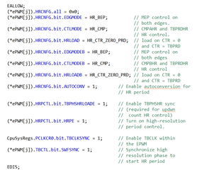
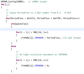
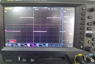
在使用C:\ti\c2000\C2000Ware_3_04_00_00\device_support\f28002x\examples\hrpwm\hrpwm_ex2_prdupdown_sfo_v8.c例程时,PWM 5Mhz频率下通过示波器能清楚观测到周期边缘位置的变化,当PWM使用50Khz频率时,基本在示波器上看不到周期边缘有变化,请问是因为高精度PWM对于其频率有最低限度要求吗?如果不是的话为什么50Khz时观测不到变化

  • 据我所知应该没有这方面的限制,但是一般来说200KHz以下的用普通PWM,200KHz以上的用HRPWM。

  • 你好,感谢您的回复,现在情况是这样的,我在做一个等离子体电源的项目,PWM频率是50Khz,主要控制TBPRD寄存器来控制频率的变化,由于普通PWM的TBPRD寄存器未Uint16格式,因此我的频率只能50hz精度的调节,如果使用高精度PWM能够实现1hz精度的频率调节吗?还有之前问您的为什么在Demo中5Mhz使用高精度可以直接在示波器中观测到,而50Khz就看不见边缘有变化?

  • HRPWM是可以实现1Hz精度的频率调节的。至于为什么50KHz的时候没有变化,我可能需要咨询一下其他工程师讨论一下。你这边方便给出对应的配置和波形图吗

  • 程序就是C2000ware中的demo程序C:\ti\c2000\C2000Ware_3_04_00_00\device_support\f28002x\examples\hrpwm\hrpwm_ex2_prdupdown_sfo_v8.c

    在不同时刻暂停,示波器上观测到的都是周期为20us的PWM波,边缘没有变化

  • 您好,请问有结果了吗?

  • 你好,还没有,有结果了尽快回复你

  • 你好,看到你的程序中配置的TBCLK = SYSCLK,那在两种开关频率下配置的TBCLK都是一样的吗?都是F280023的默认配置频率?

  • 您好,两种开关频率下配置的TBCLK都是一样的,使用的280023默认的配置频率,所有配置只更改了HRPWM_Config()函数括号里的值

  • 你好,目前还没有收到比较可靠的回复。不过我在例程主程序的开头注释中找到说明,这个例程需要在最大SYSCLKOUT下运行:

    //! To load and run this example:
    //! -# **!!IMPORTANT!!**
    //! -# Run this example at maximum SYSCLKOUT
    //! -# Activate Real time mode
    //! -# Run the code
    //! -# Watch ePWM A / B channel waveforms on a Oscilloscope
    //! -# In the watch window:
    //!    Set the variable UpdateFine = 1  to observe the ePWMxA & ePWMxB output
    //!    with HRPWM capabilities (default)
    //!    Observe the period/frequency of the waveform changes in fine MEP steps
    //! -# In the watch window:
    //!    Change the variable UpdateFine to 0, to observe the
    //!    ePWMxA & ePWMxB output without HRPWM capabilities
    //!    Observe the period/frequency of the waveform changes in coarse
    //!    SYSCLKOUT cycle steps.

  • 您好,目前是运行在SYSCLKOUT下,程序默认配置了TBCLK = SYSCLK没有更改过,PWM的时钟是用的DSP的主频,能否和工程师确认下50Khz的PWM开关频率下能否使用高精度PWM?

  • 你好,这边工程师回复,我怕翻译有误差,给你看一下原文:

    It works at 50KHz. I just tested it on my setup. It is not easy to see it on the scope. You have to:

    1. Trigger the scope on rising edge of the EPWM.

    2. Zoom into the NEXT falling edge.

    3. Change the TBPRDHR to see it changing.

    50KHz works correctly.

    //#############################################################################
    //
    // FILE:   hrpwm_ex3_prdupdown_sfo.c
    //
    // TITLE:  HRPWM Period Control.
    //
    //! \addtogroup driver_example_list
    //! <h1>HRPWM Period Control</h1>
    //!
    //! This example modifies the MEP control registers to show edge displacement
    //! for high-resolution period with ePWM in Up-Down count mode
    //! due to the HRPWM control extension of the respective ePWM module.
    //!
    //! This example calls the following TI's MEP Scale Factor Optimizer (SFO)
    //! software library V8 functions:
    //!
    //! \b int \b SFO(); \n
    //! - updates MEP_ScaleFactor dynamically when HRPWM is in use
    //! - updates HRMSTEP register (exists only in EPwm1Regs register space)
    //!   with MEP_ScaleFactor value
    //! - returns 2 if error: MEP_ScaleFactor is greater than maximum value of 255
    //!   (Auto-conversion may not function properly under this condition)
    //! - returns 1 when complete for the specified channel
    //! - returns 0 if not complete for the specified channel
    //!
    //! This example is intended to explain the HRPWM capabilities. The code can be
    //! optimized for code efficiency. Refer to TI's Digital power application
    //! examples and TI Digital Power Supply software libraries for details.
    //!
    //! \b External \b Connections \n
    //!  - Monitor ePWM1/2/3/4 A/B pins on an oscilloscope.
    //
    //#############################################################################
    // $TI Release: F28002x Support Library v3.04.00.00 $
    // $Release Date: Fri Feb 12 18:58:34 IST 2021 $
    // $Copyright:
    // Copyright (C) 2021 Texas Instruments Incorporated - http://www.ti.com/
    //
    // Redistribution and use in source and binary forms, with or without 
    // modification, are permitted provided that the following conditions 
    // are met:
    // 
    //   Redistributions of source code must retain the above copyright 
    //   notice, this list of conditions and the following disclaimer.
    // 
    //   Redistributions in binary form must reproduce the above copyright
    //   notice, this list of conditions and the following disclaimer in the 
    //   documentation and/or other materials provided with the   
    //   distribution.
    // 
    //   Neither the name of Texas Instruments Incorporated nor the names of
    //   its contributors may be used to endorse or promote products derived
    //   from this software without specific prior written permission.
    // 
    // THIS SOFTWARE IS PROVIDED BY THE COPYRIGHT HOLDERS AND CONTRIBUTORS 
    // "AS IS" AND ANY EXPRESS OR IMPLIED WARRANTIES, INCLUDING, BUT NOT 
    // LIMITED TO, THE IMPLIED WARRANTIES OF MERCHANTABILITY AND FITNESS FOR
    // A PARTICULAR PURPOSE ARE DISCLAIMED. IN NO EVENT SHALL THE COPYRIGHT 
    // OWNER OR CONTRIBUTORS BE LIABLE FOR ANY DIRECT, INDIRECT, INCIDENTAL, 
    // SPECIAL, EXEMPLARY, OR CONSEQUENTIAL DAMAGES (INCLUDING, BUT NOT 
    // LIMITED TO, PROCUREMENT OF SUBSTITUTE GOODS OR SERVICES; LOSS OF USE,
    // DATA, OR PROFITS; OR BUSINESS INTERRUPTION) HOWEVER CAUSED AND ON ANY
    // THEORY OF LIABILITY, WHETHER IN CONTRACT, STRICT LIABILITY, OR TORT 
    // (INCLUDING NEGLIGENCE OR OTHERWISE) ARISING IN ANY WAY OUT OF THE USE 
    // OF THIS SOFTWARE, EVEN IF ADVISED OF THE POSSIBILITY OF SUCH DAMAGE.
    // $
    //#############################################################################
    //
    // Included Files
    //
    #include "driverlib.h"
    #include "device.h"
    #include "board.h"
    #include "sfo_v8.h"
    
    //
    // Defines
    //
    #define EPWM_TIMER_TBPRD    1000UL
    #define LAST_EPWM_INDEX_FOR_EXAMPLE    5
    #define MIN_HRPWM_PRD_PERCENT   0.2
    
    //
    // Globals
    //
    
    float32_t periodFine = MIN_HRPWM_PRD_PERCENT;
    uint16_t status;
    
    int MEP_ScaleFactor; // Global variable used by the SFO library
                         // Result can be used for all HRPWM channels
                         // This variable is also copied to HRMSTEP
                         // register by SFO() function.
    
    volatile uint32_t ePWM[] =
        {0, myEPWM1_BASE, myEPWM2_BASE, myEPWM3_BASE, myEPWM4_BASE};
    //
    // Function Prototypes
    //
    void initHRPWM(uint32_t period);
    void error(void);
    
    //
    // Main
    //
    void main(void)
    {
        uint16_t i = 0;
    
        //
        // Initialize device clock and peripherals
        //
        Device_init();
    
        //
        // Disable pin locks and enable internal pull ups.
        //
        Device_initGPIO();
    
        //
        // Initialize PIE and clear PIE registers. Disables CPU interrupts.
        //
        Interrupt_initModule();
    
        //
        // Initialize the PIE vector table with pointers to the shell Interrupt
        // Service Routines (ISR).
        //
        Interrupt_initVectorTable();
    
        //
        // Initialize EPWM GPIOs and change XBAR inputs from using GPIO0
        //
        Board_init();
    
    
        //
        // Calling SFO() updates the HRMSTEP register with calibrated MEP_ScaleFactor.
        // HRMSTEP must be populated with a scale factor value prior to enabling
        // high resolution period control.
        //
        while(status == SFO_INCOMPLETE)
        {
            status = SFO();
            if(status == SFO_ERROR)
            {
                error();   // SFO function returns 2 if an error occurs & # of MEP
            }              // steps/coarse step exceeds maximum of 255.
        }


        //
        // Disable sync(Freeze clock to PWM as well)
        //
        SysCtl_disablePeripheral(SYSCTL_PERIPH_CLK_TBCLKSYNC);
    
        initHRPWM(EPWM_TIMER_TBPRD);
    
        //
        // Enable sync and clock to PWM
        //
        SysCtl_enablePeripheral(SYSCTL_PERIPH_CLK_TBCLKSYNC);
    
        //
        // Enable Global Interrupt (INTM) and realtime interrupt (DBGM)
        //
        EINT;
        ERTM;
    
    
        for(;;)
        {
             //
             // Sweep DutyFine
             //
             //for(periodFine = MIN_HRPWM_PRD_PERCENT; periodFine < 0.9; periodFine += 0.01)
             //{
                 DEVICE_DELAY_US(1000);
    //             for(i=1; i<LAST_EPWM_INDEX_FOR_EXAMPLE; i++)
    //             {
    //                 float32_t count = ((EPWM_TIMER_TBPRD-1) << 8UL) + (float32_t)(periodFine * 256);
    //                 uint32_t compCount = count;
    //                 HRPWM_setTimeBasePeriod(ePWM[i], compCount);
    //             }
    
                 //
                 // Call the scale factor optimizer lib function SFO()
                 // periodically to track for any change due to temp/voltage.
                 // This function generates MEP_ScaleFactor by running the
                 // MEP calibration module in the HRPWM logic. This scale
                 // factor can be used for all HRPWM channels. The SFO()
                 // function also updates the HRMSTEP register with the
                 // scale factor value.
                 //
                 status = SFO(); // in background, MEP calibration module
                                 // continuously updates MEP_ScaleFactor
    
                 if (status == SFO_ERROR)
                 {
                     error();   // SFO function returns 2 if an error occurs & #
                                // of MEP steps/coarse step
                 }              // exceeds maximum of 255.
             //}
         }
    }
    
    
    void initHRPWM(uint32_t period)
    {
    
        uint16_t j;
    
        //
        // ePWM channel register configuration with HRPWM
        //
        for (j=1;j<LAST_EPWM_INDEX_FOR_EXAMPLE;j++)
        {
            EPWM_setEmulationMode(ePWM[j], EPWM_EMULATION_FREE_RUN);
    
            //
            // Set-up TBCLK
            //
            EPWM_setPeriodLoadMode(ePWM[j], EPWM_PERIOD_SHADOW_LOAD);
            EPWM_setTimeBasePeriod(ePWM[j], period-1);
            EPWM_setPhaseShift(ePWM[j], 0U);
            EPWM_setTimeBaseCounter(ePWM[j], 0U);
    
            //
            // set duty 50% initially
            //
            HRPWM_setCounterCompareValue(ePWM[j], HRPWM_COUNTER_COMPARE_A, (period/2 << 8));
            HRPWM_setCounterCompareValue(ePWM[j], HRPWM_COUNTER_COMPARE_B, (period/2 << 8));
    
    
            //
            // Set up counter mode
            //
            EPWM_setTimeBaseCounterMode(ePWM[j], EPWM_COUNTER_MODE_UP_DOWN);
            EPWM_disablePhaseShiftLoad(ePWM[j]);
            EPWM_setClockPrescaler(ePWM[j],
                                   EPWM_CLOCK_DIVIDER_1,
                                   EPWM_HSCLOCK_DIVIDER_1);
    
            //
            // Set up shadowing
            //
            EPWM_setCounterCompareShadowLoadMode(ePWM[j],
                                                 EPWM_COUNTER_COMPARE_A,
                                                 EPWM_COMP_LOAD_ON_CNTR_ZERO);
            EPWM_setCounterCompareShadowLoadMode(ePWM[j],
                                                 EPWM_COUNTER_COMPARE_B,
                                                 EPWM_COMP_LOAD_ON_CNTR_ZERO);
    
            //
            // Set actions
            //
    
            EPWM_setActionQualifierAction(ePWM[j],
                                          EPWM_AQ_OUTPUT_A,
                                          EPWM_AQ_OUTPUT_HIGH,
                                          EPWM_AQ_OUTPUT_ON_TIMEBASE_UP_CMPA);
    
    
            EPWM_setActionQualifierAction(ePWM[j],
                                          EPWM_AQ_OUTPUT_B,
                                          EPWM_AQ_OUTPUT_HIGH,
                                          EPWM_AQ_OUTPUT_ON_TIMEBASE_UP_CMPB);
    
            EPWM_setActionQualifierAction(ePWM[j],
                                          EPWM_AQ_OUTPUT_A,
                                          EPWM_AQ_OUTPUT_LOW,
                                          EPWM_AQ_OUTPUT_ON_TIMEBASE_DOWN_CMPA);
            EPWM_setActionQualifierAction(ePWM[j],
                                          EPWM_AQ_OUTPUT_B,
                                          EPWM_AQ_OUTPUT_LOW,
                                          EPWM_AQ_OUTPUT_ON_TIMEBASE_DOWN_CMPB);
    
    
            HRPWM_setMEPEdgeSelect(ePWM[j], HRPWM_CHANNEL_A, HRPWM_MEP_CTRL_RISING_AND_FALLING_EDGE);
            HRPWM_setMEPControlMode(ePWM[j], HRPWM_CHANNEL_A, HRPWM_MEP_DUTY_PERIOD_CTRL);
            HRPWM_setCounterCompareShadowLoadEvent(ePWM[j], HRPWM_CHANNEL_A, HRPWM_LOAD_ON_CNTR_ZERO_PERIOD);
    
            HRPWM_setMEPEdgeSelect(ePWM[j], HRPWM_CHANNEL_B, HRPWM_MEP_CTRL_RISING_AND_FALLING_EDGE);
            HRPWM_setMEPControlMode(ePWM[j], HRPWM_CHANNEL_B, HRPWM_MEP_DUTY_PERIOD_CTRL);
            HRPWM_setCounterCompareShadowLoadEvent(ePWM[j], HRPWM_CHANNEL_B, HRPWM_LOAD_ON_CNTR_ZERO_PERIOD);
    
            HRPWM_enableAutoConversion(ePWM[j]);
    
            //
            // Turn on high-resolution period control.
            //
    
            HRPWM_enablePeriodControl(ePWM[j]);
            HRPWM_enablePhaseShiftLoad(ePWM[j]);
    
            EPWM_forceSyncPulse(ePWM[j]);
        }
    
    }
    
    //
    // error - Halt debugger when called
    //
    void error (void)
    {
        ESTOP0;         // Stop here and handle error
    }

    Again trigger on rising edge, zoom into the following falling edge.

    Change the TBPRDHR from 0 tp 0xE000 and see the shift.

  • 好的明白了,非常感谢您和其他工程师,谢谢!