Part Number: TMS320F2812
Other Parts Discussed in Thread: UNIFLASH, SM320F2812
你好,官方有TMS320F2812中CAN总线组网的相关资料与程序吗?我在官方例程中没找到相关的资料。另外TMS320F2812芯片如何程序烧写到片内?我没找到相关资料。
This thread has been locked.
If you have a related question, please click the "Ask a related question" button in the top right corner. The newly created question will be automatically linked to this question.
Part Number: TMS320F2812
Other Parts Discussed in Thread: UNIFLASH, SM320F2812
你好,官方有TMS320F2812中CAN总线组网的相关资料与程序吗?我在官方例程中没找到相关的资料。另外TMS320F2812芯片如何程序烧写到片内?我没找到相关资料。
您好,所有的例程都在SDK中给出了。资料基本都在芯片的详情页面给出了:https://www.ti.com.cn/product/cn/TMS320F2812
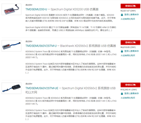
在芯片的详情页面,硬件工具中前3个为支持该芯片的仿真器:

还有TMDSEMU110-U;
也有一些第三方的仿真器。
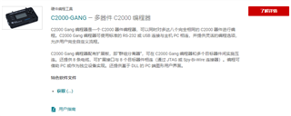
第4个C2000-GANG是量产用的烧录器:

软件的话可以用CCS开发及调试;烧录软件UNIFLASH;C2000-GANG有专门的软件。
你好,我用SM320F2812这块芯片做了一块板子,原理图如下,
在我测试仿真器连接的时候打印如下:
[Start: Texas Instruments XDS100v1 USB Debug Probe_0]
Execute the command:
%ccs_base%/common/uscif/dbgjtag -f %boarddatafile% -rv -o -F inform,logfile=yes -S pathlength -S integrity
[Result]
-----[Print the board config pathname(s)]------------------------------------
C:\Users\16508\AppData\Local\TEXASI~1\CCS\
DSP_CC~1.3_A\0\0\BrdDat\testBoard.dat
-----[Print the reset-command software log-file]-----------------------------
This utility has selected a 100- or 510-class product.
This utility will load the adapter 'jioserdesusb.dll'.
The library build date was 'Apr 8 2016'.
The library build time was '02:44:08'.
The library package version is '6.0.222.0'.
The library component version is '35.35.0.0'.
The controller does not use a programmable FPGA.
The controller has a version number of '4' (0x00000004).
The controller has an insertion length of '0' (0x00000000).
This utility will attempt to reset the controller.
This utility has successfully reset the controller.
-----[Print the reset-command hardware log-file]-----------------------------
The scan-path will be reset by toggling the JTAG TRST signal.
The controller is the FTDI FT2232 with USB interface.
The link from controller to target is direct (without cable).
The software is configured for FTDI FT2232 features.
The controller cannot monitor the value on the EMU[0] pin.
The controller cannot monitor the value on the EMU[1] pin.
The controller cannot control the timing on output pins.
The controller cannot control the timing on input pins.
The scan-path link-delay has been set to exactly '0' (0x0000).
-----[The log-file for the JTAG TCLK output generated from the PLL]----------
There is no hardware for programming the JTAG TCLK frequency.
-----[Measure the source and frequency of the final JTAG TCLKR input]--------
There is no hardware for measuring the JTAG TCLK frequency.
-----[Perform the standard path-length test on the JTAG IR and DR]-----------
This path-length test uses blocks of 64 32-bit words.
The test for the JTAG IR instruction path-length succeeded.
The JTAG IR instruction path-length is 38 bits.
The test for the JTAG DR bypass path-length succeeded.
The JTAG DR bypass path-length is 1 bits.
-----[Perform the Integrity scan-test on the JTAG IR]------------------------
This test will use blocks of 64 32-bit words.
This test will be applied just once.
Do a test using 0xFFFFFFFF.
Scan tests: 1, skipped: 0, failed: 0
Do a test using 0x00000000.
Scan tests: 2, skipped: 0, failed: 0
Do a test using 0xFE03E0E2.
Scan tests: 3, skipped: 0, failed: 0
Do a test using 0x01FC1F1D.
Scan tests: 4, skipped: 0, failed: 0
Do a test using 0x5533CCAA.
Scan tests: 5, skipped: 0, failed: 0
Do a test using 0xAACC3355.
Scan tests: 6, skipped: 0, failed: 0
All of the values were scanned correctly.
The JTAG IR Integrity scan-test has succeeded.
-----[Perform the Integrity scan-test on the JTAG DR]------------------------
This test will use blocks of 64 32-bit words.
This test will be applied just once.
Do a test using 0xFFFFFFFF.
Scan tests: 1, skipped: 0, failed: 0
Do a test using 0x00000000.
Scan tests: 2, skipped: 0, failed: 0
Do a test using 0xFE03E0E2.
Scan tests: 3, skipped: 0, failed: 0
Do a test using 0x01FC1F1D.
Scan tests: 4, skipped: 0, failed: 0
Do a test using 0x5533CCAA.
Scan tests: 5, skipped: 0, failed: 0
Do a test using 0xAACC3355.
Scan tests: 6, skipped: 0, failed: 0
All of the values were scanned correctly.
The JTAG DR Integrity scan-test has succeeded.
[End: Texas Instruments XDS100v1 USB Debug Probe_0]
中间的这部分
The controller cannot monitor the value on the EMU[0] pin.
The controller cannot monitor the value on the EMU[1] pin.
The controller cannot control the timing on output pins.
The controller cannot control the timing on input pins.
是不是有问题,我尝试在线仿真了一下,可以进入仿真的界面但是程序不动,我看这个信息,我测试了一下芯片的与板子的连接应该都是通的,尤其是下载口几个引脚的几个连接EMU[0]与EMU[1]这两个我也单独测过,发现连接没有问题,请帮我分析一下。