
Part Number: TMS320F28377D
Other Parts Discussed in Thread: SYSBIOS,
在CCS10,在Tools > RTSC Tools > Platform > Edit/View的页面下Package Name里面为什么找不到28377呢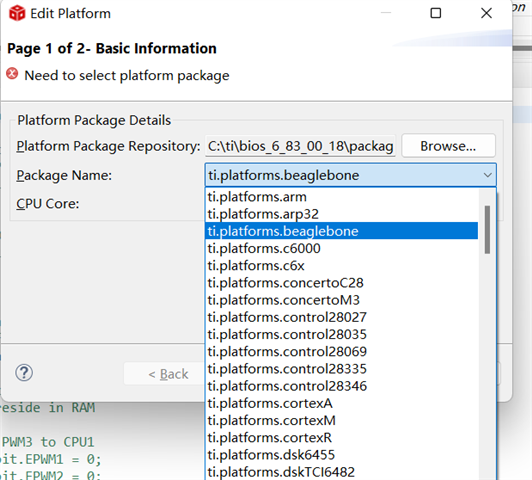

This thread has been locked.
If you have a related question, please click the "Ask a related question" button in the top right corner. The newly created question will be automatically linked to this question.
Part Number: TMS320F28377D
Other Parts Discussed in Thread: SYSBIOS,
在CCS10,在Tools > RTSC Tools > Platform > Edit/View的页面下Package Name里面为什么找不到28377呢

"我们的工程师不明白问题出在哪里——Hwi模块有什么问题?添加后程序以何种方式失败?"
我使用了hwi模块,用EPWM1简单做了一个中断,代码烧录进去点击运行之后,代码自己停在了下图
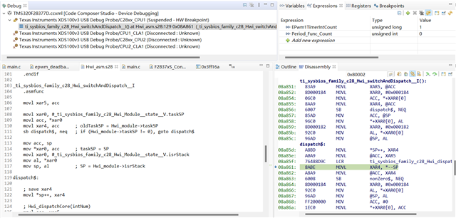
我把我的代码附上,麻烦帮忙看看是哪里的问题,谢谢
main函数如下:
void main(void)
{
    DINT; // Disable global interrupts
    DRTM;

    InitSysCtrl();

    IER = 0x0000;
    IFR = 0x0000;

    Uint8 i = 0;
    for(i = 0; i < 5; i++)
    {
        DELAY_US(1000000);
    }
    CpuSysRegs.PCLKCR2.bit.EPWM1=1;

    InitEPwm1Gpio();

    EALLOW;
    CpuSysRegs.PCLKCR0.bit.TBCLKSYNC =0;
    EDIS;

    InitEPwm1Example();

    EALLOW;
    CpuSysRegs.PCLKCR0.bit.TBCLKSYNC =1;
    EDIS;


    EINT;  // Enable Global interrupt INTM
    ERTM;  // Enable Global realtime interrupt DBGM
    //EnableInnerDog();               // Enable Inner Software Watchdog

    Hwi_enableInterrupt(48);
    BIOS_start();    /* does not return */

}
PLL和外设时钟使能
void InitSysCtrl(void)
{
    // Disable the watchdog
    DisableDog();

#ifdef _FLASH
// Copy time critical code and Flash setup code to RAM
// This includes the following functions:  InitFlash();
// The  RamfuncsLoadStart, RamfuncsLoadSize, and RamfuncsRunStart
// symbols are created by the linker. Refer to the device .cmd file.
    memcpy(&RamfuncsRunStart, &RamfuncsLoadStart, (size_t)&RamfuncsLoadSize);

// Call Flash Initialization to setup flash waitstates
// This function must reside in RAM
    InitFlash();
#endif

    // *IMPORTANT*
    // The Device_cal function, which copies the ADC & oscillator calibration values
    // from TI reserved OTP into the appropriate trim registers, occurs automatically
    // in the Boot ROM. If the boot ROM code is bypassed during the debug process, the
    // following function MUST be called for the ADC and oscillators to function according
    // to specification. The clocks to the ADC MUST be enabled before calling this
    // function.
    // See the device data manual and/or the ADC Reference
    // Manual for more information.
#ifdef CPU1
    EALLOW;

    //enable pull-ups on unbonded IOs as soon as possible to reduce power consumption.
    GPIO_EnableUnbondedIOPullups();

	CpuSysRegs.PCLKCR13.bit.ADC_A = 1;
	CpuSysRegs.PCLKCR13.bit.ADC_B = 1;
	CpuSysRegs.PCLKCR13.bit.ADC_C = 1;
	CpuSysRegs.PCLKCR13.bit.ADC_D = 1;

    //check if device is trimmed
    if(*((Uint16 *)0x5D1B6) == 0x0000){
        //device is not trimmed, apply static calibration values
        AnalogSubsysRegs.ANAREFTRIMA.all = 31709;
        AnalogSubsysRegs.ANAREFTRIMB.all = 31709;
        AnalogSubsysRegs.ANAREFTRIMC.all = 31709;
        AnalogSubsysRegs.ANAREFTRIMD.all = 31709;
    }

	CpuSysRegs.PCLKCR13.bit.ADC_A = 0;
	CpuSysRegs.PCLKCR13.bit.ADC_B = 0;
	CpuSysRegs.PCLKCR13.bit.ADC_C = 0;
	CpuSysRegs.PCLKCR13.bit.ADC_D = 0;
    EDIS;

    // Initialize the PLL control: PLLCR and CLKINDIV
    // F28_PLLCR and F28_CLKINDIV are defined in F2837xD_Examples.h
    // Note: The internal oscillator CANNOT be used as the PLL source if the
    // PLLSYSCLK is configured to frequencies above 194 MHz.
    InitSysPll(XTAL_OSC,IMULT_20,FMULT_0,PLLCLK_BY_2); 		//PLLSYSCLK = (XTAL_OSC) * (IMULT + FMULT) / (PLLSYSCLKDIV)

#endif

    //Turn on all peripherals
	InitPeripheralClocks();
}

//---------------------------------------------------------------------------
// InitPeripheralClocks
//---------------------------------------------------------------------------
// This function initializes the clocks for the peripherals.
//
// Note: In order to reduce power consumption, turn off the clocks to any
// peripheral that is not specified for your part-number or is not used in the
// application
void InitPeripheralClocks()
{
	EALLOW;

	CpuSysRegs.PCLKCR0.bit.CLA1 = 1;
	CpuSysRegs.PCLKCR0.bit.DMA = 1;
	CpuSysRegs.PCLKCR0.bit.CPUTIMER0 = 1;
	CpuSysRegs.PCLKCR0.bit.CPUTIMER1 = 1;
	CpuSysRegs.PCLKCR0.bit.CPUTIMER2 = 1;

#ifdef CPU1
	CpuSysRegs.PCLKCR0.bit.HRPWM = 1;
#endif

	CpuSysRegs.PCLKCR0.bit.TBCLKSYNC = 1;

#ifdef CPU1
	CpuSysRegs.PCLKCR1.bit.EMIF1 = 1;
	CpuSysRegs.PCLKCR1.bit.EMIF2 = 1;
#endif

	CpuSysRegs.PCLKCR2.bit.EPWM1 = 1;
	CpuSysRegs.PCLKCR2.bit.EPWM2 = 1;
	CpuSysRegs.PCLKCR2.bit.EPWM3 = 1;
	CpuSysRegs.PCLKCR2.bit.EPWM4 = 1;
	CpuSysRegs.PCLKCR2.bit.EPWM5 = 1;
	CpuSysRegs.PCLKCR2.bit.EPWM6 = 1;
	CpuSysRegs.PCLKCR2.bit.EPWM7 = 1;
	CpuSysRegs.PCLKCR2.bit.EPWM8 = 1;
	CpuSysRegs.PCLKCR2.bit.EPWM9 = 1;
	CpuSysRegs.PCLKCR2.bit.EPWM10 = 1;
	CpuSysRegs.PCLKCR2.bit.EPWM11 = 1;
	CpuSysRegs.PCLKCR2.bit.EPWM12 = 1;

	CpuSysRegs.PCLKCR3.bit.ECAP1 = 1;
	CpuSysRegs.PCLKCR3.bit.ECAP2 = 1;
	CpuSysRegs.PCLKCR3.bit.ECAP3 = 1;
	CpuSysRegs.PCLKCR3.bit.ECAP4 = 1;
	CpuSysRegs.PCLKCR3.bit.ECAP5 = 1;
	CpuSysRegs.PCLKCR3.bit.ECAP6 = 1;

	CpuSysRegs.PCLKCR4.bit.EQEP1 = 1;
	CpuSysRegs.PCLKCR4.bit.EQEP2 = 1;
	CpuSysRegs.PCLKCR4.bit.EQEP3 = 1;

	CpuSysRegs.PCLKCR6.bit.SD1 = 1;
	CpuSysRegs.PCLKCR6.bit.SD2 = 1;

	CpuSysRegs.PCLKCR7.bit.SCI_A = 1;
	CpuSysRegs.PCLKCR7.bit.SCI_B = 1;
	CpuSysRegs.PCLKCR7.bit.SCI_C = 1;
	CpuSysRegs.PCLKCR7.bit.SCI_D = 1;

	CpuSysRegs.PCLKCR8.bit.SPI_A = 1;
	CpuSysRegs.PCLKCR8.bit.SPI_B = 1;
	CpuSysRegs.PCLKCR8.bit.SPI_C = 1;

	CpuSysRegs.PCLKCR9.bit.I2C_A = 1;
	CpuSysRegs.PCLKCR9.bit.I2C_B = 1;

	CpuSysRegs.PCLKCR10.bit.CAN_A = 1;
	CpuSysRegs.PCLKCR10.bit.CAN_B = 1;

	CpuSysRegs.PCLKCR11.bit.McBSP_A = 1;
	CpuSysRegs.PCLKCR11.bit.McBSP_B = 1;

#ifdef CPU1
	CpuSysRegs.PCLKCR11.bit.USB_A = 1;

	CpuSysRegs.PCLKCR12.bit.uPP_A = 1;
#endif

	CpuSysRegs.PCLKCR13.bit.ADC_A = 1;
	CpuSysRegs.PCLKCR13.bit.ADC_B = 1;
	CpuSysRegs.PCLKCR13.bit.ADC_C = 1;
	CpuSysRegs.PCLKCR13.bit.ADC_D = 1;

	CpuSysRegs.PCLKCR14.bit.CMPSS1 = 1;
	CpuSysRegs.PCLKCR14.bit.CMPSS2 = 1;
	CpuSysRegs.PCLKCR14.bit.CMPSS3 = 1;
	CpuSysRegs.PCLKCR14.bit.CMPSS4 = 1;
	CpuSysRegs.PCLKCR14.bit.CMPSS5 = 1;
	CpuSysRegs.PCLKCR14.bit.CMPSS6 = 1;
	CpuSysRegs.PCLKCR14.bit.CMPSS7 = 1;
	CpuSysRegs.PCLKCR14.bit.CMPSS8 = 1;

	CpuSysRegs.PCLKCR16.bit.DAC_A = 1;
	CpuSysRegs.PCLKCR16.bit.DAC_B = 1;
	CpuSysRegs.PCLKCR16.bit.DAC_C = 1;

	EDIS;
}
GPIO配置
void InitEPwm1Gpio(void)
{
    EALLOW;

    //
    // Disable internal pull-up for the selected output pins
    // for reduced power consumption
    // Pull-ups can be enabled or disabled by the user.
    // Comment out other unwanted lines.
    //
    GpioCtrlRegs.GPAPUD.bit.GPIO0 = 1;    // Disable pull-up on GPIO0 (EPWM1A)
    GpioCtrlRegs.GPAPUD.bit.GPIO1 = 1;    // Disable pull-up on GPIO1 (EPWM1B)
    GpioCtrlRegs.GPAPUD.bit.GPIO2 = 0;    // Disable pull-up on GPIO0 (EPWM1A)
    GpioCtrlRegs.GPAPUD.bit.GPIO3 = 0;    // Disable pull-up on GPIO1 (EPWM1B)
    // GpioCtrlRegs.GPEPUD.bit.GPIO145 = 1;    // Disable pull-up on GPIO145 (EPWM1A)
    // GpioCtrlRegs.GPEPUD.bit.GPIO146 = 1;    // Disable pull-up on GPIO146 (EPWM1B)

    //
    // Configure EPWM-1 pins using GPIO regs
    // This specifies which of the possible GPIO pins will be EPWM1 functional
    // pins.
    // Comment out other unwanted lines.
    //
    GpioCtrlRegs.GPAMUX1.bit.GPIO0 = 1;   // Configure GPIO0 as EPWM1A
    GpioCtrlRegs.GPAMUX1.bit.GPIO1 = 1;   // Configure GPIO1 as EPWM1B
    GpioCtrlRegs.GPAMUX1.bit.GPIO2 = 0;   // Configure GPIO0 as EPWM1A
    GpioCtrlRegs.GPAMUX1.bit.GPIO3 = 0;   // Configure GPIO1 as EPWM1B

    GpioCtrlRegs.GPAMUX1.bit.GPIO2 = 0;  // GPIO
    GpioCtrlRegs.GPADIR.bit.GPIO2 = 1;   // GPIO34 = output
    GpioDataRegs.GPACLEAR.bit.GPIO2 = 1;
    GpioCtrlRegs.GPAMUX1.bit.GPIO3 = 0;  // GPIO
    GpioCtrlRegs.GPADIR.bit.GPIO3 = 1;   // GPIO34 = output
    GpioDataRegs.GPACLEAR.bit.GPIO3 = 1;
    // GpioCtrlRegs.GPEMUX2.bit.GPIO145 = 1;   // Configure GPIO145 as EPWM1A
    // GpioCtrlRegs.GPEMUX2.bit.GPIO146 = 1;   // Configure GPIO0146 as EPWM1B

    EDIS;
}
EPWM模块配置:使用pwm模块输出一对pwm,并触发PWM中断
void InitEPwm1Example()
{
    EPwm1Regs.TBPRD = 6000;                       // Set timer period
    EPwm1Regs.TBPHS.bit.TBPHS = 0x0000;           // Phase is 0
    EPwm1Regs.TBCTR = 0x0000;                     // Clear counter

    // Setup TBCLK
    EPwm1Regs.TBCTL.bit.CTRMODE = TB_COUNT_UPDOWN; // Count up
    EPwm1Regs.TBCTL.bit.PHSEN = TB_DISABLE;        // Disable phase loading
    EPwm1Regs.TBCTL.bit.HSPCLKDIV = TB_DIV4;       // Clock ratio to SYSCLKOUT
    EPwm1Regs.TBCTL.bit.CLKDIV = TB_DIV4;

    EPwm1Regs.CMPCTL.bit.SHDWAMODE = CC_SHADOW;   // Load registers every ZERO
    EPwm1Regs.CMPCTL.bit.SHDWBMODE = CC_SHADOW;
    EPwm1Regs.CMPCTL.bit.LOADAMODE = CC_CTR_ZERO;
    EPwm1Regs.CMPCTL.bit.LOADBMODE = CC_CTR_ZERO;

    // Setup compare
    EPwm1Regs.CMPA.bit.CMPA = 3000;

    // Set actions
    EPwm1Regs.AQCTLA.bit.CAU = AQ_SET;            // Set PWM1A on Zero
    EPwm1Regs.AQCTLA.bit.CAD = AQ_CLEAR;

    EPwm1Regs.AQCTLB.bit.CAU = AQ_CLEAR;         // Set PWM1A on Zero
    EPwm1Regs.AQCTLB.bit.CAD = AQ_SET;

    // Active Low PWMs - Setup Deadband
    EPwm1Regs.DBCTL.bit.OUT_MODE = DB_FULL_ENABLE;
    EPwm1Regs.DBCTL.bit.POLSEL = DB_ACTV_LO;
    EPwm1Regs.DBCTL.bit.IN_MODE = DBA_ALL;
    EPwm1Regs.DBRED.bit.DBRED = 0;
    EPwm1Regs.DBFED.bit.DBFED = 0;

    // Interrupt where we will change the Deadband
    EPwm1Regs.ETSEL.bit.INTSEL = ET_CTR_ZERO;    // Select INT on Zero event
    EPwm1Regs.ETSEL.bit.INTEN = 1;               // Enable INT
    EPwm1Regs.ETPS.bit.INTPRD = ET_3RD;          // Generate INT on 3rd event

}
PWM中断服务函数:
// 3.1 - ePWM1 Interrupt
Void EPWM1_ISR()
{
    //Hwi_clearInterrupt(48);
    GpioDataRegs.GPATOGGLE.bit.GPIO3 = 1;

    EPwm1TimerIntCount++;
    if(EPwm1TimerIntCount > 1000)
    {
        EPwm1TimerIntCount = 0;
    }
    // Clear INT flag for this timer
    EPwm1Regs.ETCLR.bit.INT = 1;

    // Acknowledge this interrupt to receive more interrupts from group 3
   PieCtrlRegs.PIEACK.all = PIEACK_GROUP3;
     //Hwi_enableInterrupt(48);
}
BIOS配置
var Defaults = xdc.useModule('xdc.runtime.Defaults');
var Diags = xdc.useModule('xdc.runtime.Diags');
var Error = xdc.useModule('xdc.runtime.Error');
var Log = xdc.useModule('xdc.runtime.Log');
var LoggerBuf = xdc.useModule('xdc.runtime.LoggerBuf');
var Main = xdc.useModule('xdc.runtime.Main');
var SysMin = xdc.useModule('xdc.runtime.SysMin');
var System = xdc.useModule('xdc.runtime.System');
var Text = xdc.useModule('xdc.runtime.Text');

var BIOS = xdc.useModule('ti.sysbios.BIOS');
var Clock = xdc.useModule('ti.sysbios.knl.Clock');

var Hwi = xdc.useModule('ti.sysbios.family.c28.Hwi');
var Boot = xdc.useModule('ti.catalog.c2800.initF2837x.Boot');
var ti_sysbios_hal_Hwi = xdc.useModule('ti.sysbios.hal.Hwi');

/*
 * Uncomment this line to globally disable Asserts.
 * All modules inherit the default from the 'Defaults' module.  You
 * can override these defaults on a per-module basis using Module.common$.
 * Disabling Asserts will save code space and improve runtime performance.
Defaults.common$.diags_ASSERT = Diags.ALWAYS_OFF;
 */

/*
 * Uncomment this line to keep module names from being loaded on the target.
 * The module name strings are placed in the .const section. Setting this
 * parameter to false will save space in the .const section.  Error and
 * Assert messages will contain an "unknown module" prefix instead
 * of the actual module name.
Defaults.common$.namedModule = false;
 */

/*
 * Minimize exit handler array in System.  The System module includes
 * an array of functions that are registered with System_atexit() to be
 * called by System_exit().
 */
System.maxAtexitHandlers = 4;

/*
 * Uncomment this line to disable the Error print function.
 * We lose error information when this is disabled since the errors are
 * not printed.  Disabling the raiseHook will save some code space if
 * your app is not using System_printf() since the Error_print() function
 * calls System_printf().
Error.raiseHook = null;
 */

/*
 * Uncomment this line to keep Error, Assert, and Log strings from being
 * loaded on the target.  These strings are placed in the .const section.
 * Setting this parameter to false will save space in the .const section.
 * Error, Assert and Log message will print raw ids and args instead of
 * a formatted message.
Text.isLoaded = false;
 */

/*
 * Uncomment this line to disable the output of characters by SysMin
 * when the program exits.  SysMin writes characters to a circular buffer.
 * This buffer can be viewed using the SysMin Output view in ROV.
SysMin.flushAtExit = false;
 */

/*
 * The BIOS module will create the default heap for the system.
 * Specify the size of this default heap.
 */
BIOS.heapSize = 4096;

/*
 * Build a custom SYS/BIOS library from sources.
 */
BIOS.libType = BIOS.LibType_Custom;

/* System stack size (used by ISRs and Swis) */
Program.stack = 4096;

/* Circular buffer size for System_printf() */
SysMin.bufSize = 0x200;

/*
 * Create and install logger for the whole system
 */
var loggerBufParams = new LoggerBuf.Params();
loggerBufParams.numEntries = 32;
var logger0 = LoggerBuf.create(loggerBufParams);
Defaults.common$.logger = logger0;
Main.common$.diags_INFO = Diags.ALWAYS_ON;

System.SupportProxy = SysMin;
var clock0Params = new Clock.Params();
clock0Params.instance.name = "clock0";
clock0Params.period = 2;
clock0Params.startFlag = true;
Program.global.clock0 = Clock.create("&Per_Fuction2ms", 2, clock0Params);
BIOS.cpuFreq.lo = 200000000;
Boot.OSCCLKSRCSEL = Boot.OscClk_XTAL;
Boot.OSCCLK = 20;
Boot.SPLLIMULT = 20;
Boot.SYSCLKDIVSEL = 1;
Boot.bootFromFlash = false;
Boot.configureClocks = false;
Boot.SPLLFMULT = Boot.Fract_0;
Clock.timerId = -1;
Clock.swiPriority = 15;
var ti_sysbios_hal_Hwi0Params = new ti_sysbios_hal_Hwi.Params();
ti_sysbios_hal_Hwi0Params.instance.name = "ti_sysbios_hal_Hwi0";
Program.global.ti_sysbios_hal_Hwi0 = ti_sysbios_hal_Hwi.create(48, "&EPWM1_ISR", ti_sysbios_hal_Hwi0Params);
Boot.configSharedRAMs = false;
ti_sysbios_hal_Hwi.dispatcherAutoNestingSupport = false;
Boot.loadSegment = "PRGO PAGE = 0";
Boot.runSegment = "User_RAM PAGE = 1";
Boot.disableWatchdog = true;
CMD文件
MEMORY
{
PAGE 0 :  /* Program Memory */
          /* BEGIN is used for the "boot to FLASH" bootloader mode   */

    D01SARAM   : origin = 0x00B000, length = 0x001000

    /* Flash boot address */
    BEGIN   : origin = 0x080000, length = 0x000002

    /* Flash sectors */
    PRGO  : origin = 0x080002, length = 0x03FFFE  /* on-chip Flash */
   /* FLASHB  : origin = 0x082000, length = 0x002000 */ /* on-chip Flash */
   /* FLASHC  : origin = 0x084000, length = 0x002000 */ /* on-chip Flash */
   /* FLASHD  : origin = 0x086000, length = 0x002000*/  /* on-chip Flash */
   /* FLASHE  : origin = 0x088000, length = 0x008000 */ /* on-chip Flash */
   /* FLASHF  : origin = 0x090000, length = 0x008000 */ /* on-chip Flash */
   /* FLASHG  : origin = 0x098000, length = 0x008000*/  /* on-chip Flash */
   /* FLASHH  : origin = 0x0A0000, length = 0x008000 */ /* on-chip Flash */
   /* FLASHI  : origin = 0x0A8000, length = 0x008000 */ /* on-chip Flash */
   /* FLASHJ  : origin = 0x0B0000, length = 0x008000 */ /* on-chip Flash */
   /* FLASHK  : origin = 0x0B8000, length = 0x002000 */ /* on-chip Flash */
   /* FLASHL  : origin = 0x0BA000, length = 0x002000 */ /* on-chip Flash */
   /* FLASHM  : origin = 0x0BC000, length = 0x002000 */ /* on-chip Flash */
   /* FLASHN  : origin = 0x0BE000, length = 0x002000*/  /* on-chip Flash */
    RESET   : origin = 0x3FFFC0, length = 0x000002

PAGE 1 : /* Data Memory */

    BOOT_RSVD : origin = 0x000002, length = 0x000120 /* Part of M0, BOOT rom
                                                        will use this for
                                                        stack */

    M01SARAM : origin = 0x000122, length = 0x0006DE  /* on-chip RAM */

  /*  LS05SARAM : origin = 0x008000, length = 0x003000*/ /* on-chip RAM */

    /* on-chip Global shared RAMs */
   /* RAMGS0  : origin = 0x00C000, length = 0x001000*/
   /* RAMGS1  : origin = 0x00D000, length = 0x001000*/
   /* RAMGS2  : origin = 0x00E000, length = 0x001000*/
   /* RAMGS3  : origin = 0x00F000, length = 0x001000*/
   /* RAMGS4  : origin = 0x010000, length = 0x001000*/
   /* RAMGS5  : origin = 0x011000, length = 0x001000*/
   /* RAMGS6  : origin = 0x012000, length = 0x001000*/
   /* RAMGS7  : origin = 0x013000, length = 0x001000*/
   /* RAMGS8  : origin = 0x014000, length = 0x001000*/
   /* RAMGS9  : origin = 0x015000, length = 0x001000*/
   /* RAMGS10 : origin = 0x016000, length = 0x001000*/
   /* RAMGS11 : origin = 0x017000, length = 0x001000*/
   /* RAMGS12 : origin = 0x018000, length = 0x001000*/
   /* RAMGS13 : origin = 0x019000, length = 0x001000*/
   /* RAMGS14 : origin = 0x01A000, length = 0x001000*/
   /* RAMGS15 : origin = 0x01B000, length = 0x001000*/

	User_RAM : origin = 0x008000, length = 0x013000

    /* Shared MessageRam */
    CPU2TOCPU1RAM   : origin = 0x03F800, length = 0x000400
    CPU1TOCPU2RAM   : origin = 0x03FC00, length = 0x000400
}


SECTIONS
{
    /* Allocate program areas: */
    .cinit              : > PRGO PAGE = 0
    .binit              : > PRGO PAGE = 0
#ifdef __TI_EABI__
    .init_array         : > PRGO PAGE = 0
#else
    .pinit              : > PRGO PAGE = 0
#endif
    .text               : > PRGO PAGE = 0
    codestart           : > BEGIN   PAGE = 0
    ramfuncs            : LOAD = PRGO PAGE = 0
                          RUN  = User_RAM  PAGE = 1
                          LOAD_START(_RamfuncsLoadStart),
                          LOAD_SIZE(_RamfuncsLoadSize),
                          LOAD_END(_RamfuncsLoadEnd),
                          RUN_START(_RamfuncsRunStart),
                          RUN_SIZE(_RamfuncsRunSize),
                          RUN_END(_RamfuncsRunEnd)

#ifdef __TI_COMPILER_VERSION__
#if __TI_COMPILER_VERSION__ >= 15009000
    .TI.ramfunc : {} LOAD = PRGO PAGE = 0,
                     RUN  = User_RAM PAGE = 1,
                     table(BINIT)
#endif
#endif

    /* Allocate uninitalized data sections: */
    .stack              : > User_RAM    PAGE = 1
#ifdef __TI_EABI__
    .bss                : > User_RAM    PAGE = 1
    .sysmem             : > User_RAM    PAGE = 1
#else
    .ebss               : > User_RAM    PAGE = 1
    .esysmem            : > User_RAM    PAGE = 1
#endif
    .data               : > User_RAM    PAGE = 1
    .cio                : > User_RAM    PAGE = 1

    /* Initalized sections go in Flash */
#ifdef __TI_EABI__
    .const              : > PRGO PAGE = 0
#else
    .econst             : > PRGO PAGE = 0
#endif
    .switch             : > PRGO PAGE = 0
    .args               : > PRGO PAGE = 0

    Filter_RegsFile     : > User_RAM PAGE = 1

    /* The following section definitions are required when using the IPC API Drivers */
    GROUP : > CPU1TOCPU2RAM, PAGE = 1
    {
        PUTBUFFER
        PUTWRITEIDX
        GETREADIDX
    }

    GROUP : > CPU2TOCPU1RAM, PAGE = 1
    {
        GETBUFFER :    TYPE = DSECT
        GETWRITEIDX :  TYPE = DSECT
        PUTREADIDX :   TYPE = DSECT
    }
}
所以程序是陷入了Hwi调度例程内的循环吗?这个问题是在调用 BIOS_start 之前还是之后发生的?是否检查过 ROV 的 Hwi 状态或任何报告的错误?
是陷入了hwi调度那里,BIOS_Start之后发生的,ROV怎么使用?使用ROV时提示Error: ROV only supports Elf object files,请问这个文件是编译器生成的吗?一般存放在哪呢?

