Part Number: TMS320F28379D
您好,
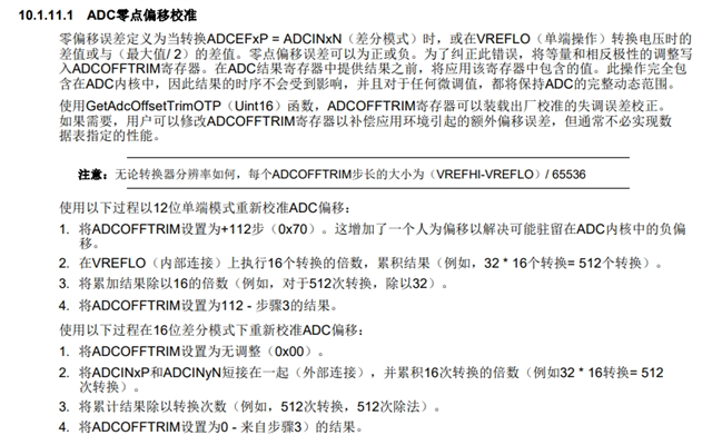
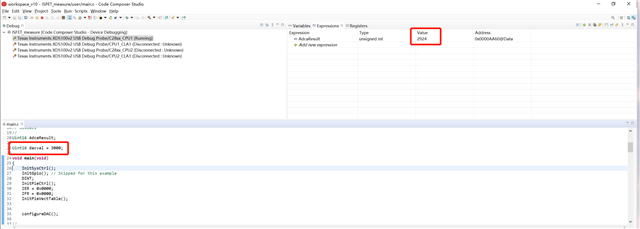
我在用28379D Launch Pad的ADC读取DAC输出时结果对不上,如下图DAC输出3000.ADC读取为2924
请问这个该如何校准?
下面是我的代码
//
// Included Files
//
#include "F28x_Project.h"

typedef unsigned char Uint8;
//
// Function Prototypes
//
void ConfigureADC(void);
void SetupADCContinuous();

void configureDAC();

void gpio_init();

//
// Globals
//
Uint16 AdcaResult;

Uint16 dacval = 3000;

void main(void)
{
    InitSysCtrl();
    InitGpio(); // Skipped for this example
    DINT;
    InitPieCtrl();
    IER = 0x0000;
    IFR = 0x0000;
    InitPieVectTable();


    configureDAC();

//
// Configure the ADC and power it up
//
    ConfigureADC();

//
// Setup the ADC for continuous conversions on channel 0
//
    SetupADCContinuous();

//
// Enable global Interrupts and higher priority real-time debug events:
//
    EINT;  // Enable Global interrupt INTM
    ERTM;  // Enable Global realtime interrupt DBGM

//
// take conversions indefinitely in loop
//
    do
    {
        DacaRegs.DACVALS.all = dacval;//选DAC?
        DELAY_US(2);

        //
        //enable ADCINT flags
        //
        EALLOW;
        AdcaRegs.ADCINTSEL1N2.bit.INT2E = 1;
        AdcaRegs.ADCINTFLGCLR.all = 0x0002;
        EDIS;

        //
        //software force start SOC0
        //
        AdcaRegs.ADCSOCFRC1.all = 0x0001;


        AdcaResult = AdcaResultRegs.ADCRESULT0;

        //
        //disable all ADCINT flags to stop sampling
        //
        EALLOW;
        AdcaRegs.ADCINTSEL1N2.bit.INT2E = 0;
        EDIS;

    }while(1);
}

//
// ConfigureADC - Write ADC configurations and power up the ADC for both
//                ADC A and ADC B
//
void ConfigureADC(void)
{
    EALLOW;

    //
    //write configurations
    //
    AdcaRegs.ADCCTL2.bit.PRESCALE = 6; //set ADCCLK divider to /4
    AdcSetMode(ADC_ADCA, ADC_RESOLUTION_12BIT, ADC_SIGNALMODE_SINGLE);

    //
    //Set pulse positions to late
    //
    AdcaRegs.ADCCTL1.bit.INTPULSEPOS = 1;

    //
    //power up the ADC
    //
    AdcaRegs.ADCCTL1.bit.ADCPWDNZ = 1;

    //
    //delay for 1ms to allow ADC time to power up
    //
    DELAY_US(1000);

    EDIS;
}

//
// SetupADCContinuous - setup the ADC to continuously convert on one channel
//
void SetupADCContinuous()
{
    Uint16 acqps;

    //
    // Determine minimum acquisition window (in SYSCLKS) based on resolution
    //
    if(ADC_RESOLUTION_12BIT == AdcaRegs.ADCCTL2.bit.RESOLUTION)
    {
        acqps = 14; //75ns
    }
    else //resolution is 16-bit
    {
        acqps = 63; //320ns
    }

    EALLOW;
    AdcaRegs.ADCSOC0CTL.bit.CHSEL  = 2;  //SOC will convert on channel A2

    AdcaRegs.ADCSOC0CTL.bit.ACQPS  = acqps;    //sample window is acqps +
                                               //1 SYSCLK cycles

    AdcaRegs.ADCINTSEL1N2.bit.INT2E = 0; //disable INT2 flag

    AdcaRegs.ADCINTSEL1N2.bit.INT2CONT = 0;

    AdcaRegs.ADCINTSEL1N2.bit.INT2SEL = 14; //end of SOC14 will set INT2 flag

    //
    //ADCINT2 will trigger first 8 SOCs
    //
    AdcaRegs.ADCINTSOCSEL1.bit.SOC0 = 2;

    EDIS;
}

void configureDAC()
{
    EALLOW;
    DacaRegs.DACCTL.bit.DACREFSEL = 1;//参考电压选择 0:VDAC/VSSA 1:VREFHI/VREFLO
    DacaRegs.DACOUTEN.bit.DACOUTEN = 1;//DAC输出使能
    DacaRegs.DACVALS.all = 0;//影子寄存器
    DELAY_US(10); // Delay for buffered DAC to power up
    EDIS;
}