Part Number: TMS320F28388D
自己设计的28388D电路板
使用串口A与430单片机通讯,使用串口B与上位机软件通讯
在spi_ex1_loopback例程基础上建立的工程
工程分为RAM版本和Flash版本,调试时ram版本没有问题,flash版本在烧录后利用仿真器调试功能也是正常的。
烧录flash后,电路板断电,移除仿真器,在上电,1秒闪烁一次的2个指示灯是正常的,系统里面配置了cputimer控制灯的闪烁,但是上位机串口发送指令后,388没有响应
我没有深究这个问题,感觉不是太好查,所以我尝试了在初始化系统后,加了一个100mS的大延时,在继续后面的初始化,串口通讯就是正常的了
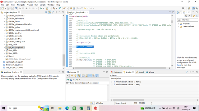
如上图所示,我在这个位置加了延时
InitSysCtrl函数的定义如下:
//
// InitSysCtrl - Initialization of system resources.
//
void InitSysCtrl(void)
{
//
// Disable the watchdog
//
DisableDog();
#ifdef _FLASH
//
// Copy time critical code and Flash setup code to RAM. This includes the
// following functions: InitFlash()
//
// The RamfuncsLoadStart, RamfuncsLoadSize, and RamfuncsRunStart
// symbols are created by the linker. Refer to the device .cmd file.
//
memcpy(&RamfuncsRunStart, &RamfuncsLoadStart, (size_t)&RamfuncsLoadSize);
//
// Call Flash Initialization to setup flash waitstates. This function must
// reside in RAM.
//
InitFlash();
#endif
//
// *IMPORTANT*
//
// The Device_cal function, which copies the ADC & oscillator calibration
// values from TI reserved OTP into the appropriate trim registers, occurs
// automatically in the Boot ROM. If the boot ROM code is bypassed during
// the debug process, the following function MUST be called for the ADC and
// oscillators to function according to specification. The clocks to the
// ADC MUST be enabled before calling this function.
//
// See the device data manual and/or the ADC Reference Manual for more
// information.
//
#ifdef CPU1
//
// Enable pull-ups on unbonded IOs as soon as possible to reduce power
// consumption.
//
GPIO_EnableUnbondedIOPullups();
EALLOW;
CpuSysRegs.PCLKCR13.bit.ADC_A = 1;
CpuSysRegs.PCLKCR13.bit.ADC_B = 1;
CpuSysRegs.PCLKCR13.bit.ADC_C = 1;
CpuSysRegs.PCLKCR13.bit.ADC_D = 1;
//
// Check if device is trimmed
//
if(*((Uint16 *)0x5D736) == 0x0000){
//
// Device is not trimmed--apply static calibration values
//
AnalogSubsysRegs.ANAREFTRIMA.all = 31709;
AnalogSubsysRegs.ANAREFTRIMB.all = 31709;
AnalogSubsysRegs.ANAREFTRIMC.all = 31709;
AnalogSubsysRegs.ANAREFTRIMD.all = 31709;
}
CpuSysRegs.PCLKCR13.bit.ADC_A = 0;
CpuSysRegs.PCLKCR13.bit.ADC_B = 0;
CpuSysRegs.PCLKCR13.bit.ADC_C = 0;
CpuSysRegs.PCLKCR13.bit.ADC_D = 0;
EDIS;
//
// Verify the crystal frequency.
// Note: This check can be removed if you are not using XTAL as the PLL
// source
//
if(!VerifyXTAL(OSC_FREQ))
{
//
// The actual XTAL frequency does not match OSC_FREQ!!
// Please check the XTAL frequency used.
//
// By default, the InitSysCtrl function assumes 25MHz XTAL.
// If a 20MHz crystal is used, please add a predefined symbol
// "USE_20MHZ_XTAL" in your CCS project.
// If a different XTAL is used, please update the PLL configuration
// below accordingly.
//
// Note that the latest F2838x controlCARDs (Rev.B and later) have been
// updated to use 25MHz XTAL by default. If you have an older 20MHz XTAL
// controlCARD (E1, E2, or Rev.A), refer to the controlCARD
// documentation on steps to reconfigure the controlCARD from 20MHz to
// 25MHz.
//
ESTOP0;
while(1);
}
//
// Initialize the SYSPLL control to generate a 200Mhz clock
//
// Defined options to be passed as arguments to this function are defined
// in f2838x_examples.h.
//
// Note: The internal oscillator CANNOT be used as the PLL source if the
// PLLSYSCLK is configured to frequencies above 194 MHz.
//
// PLLSYSCLK = (XTAL_OSC) * (IMULT) /(REFDIV) * (ODIV) * (PLLSYSCLKDIV)
//
InitSysPll(XTAL_OSC_SE, SYS_IMULT, SYS_REFDIV, SYS_ODIV, SYS_DIV, SYSCTL_DCC_BASE0);
//
// Initialize the AUXPLL control to generate a 125Mhz clock:
//
// Defined options to be passed as arguments to this function are defined
// in f2838x_Examples.h.
//
// Note: The internal oscillator CANNOT be used as the PLL source if the
// AUXPLLCLK is configured to frequencies above 194 MHz.
//
// AUXPLLCLK = (XTAL_OSC) * (IMULT) /(REFDIV) * (ODIV) * (AUXPLLDIV)
//
InitAuxPll(XTAL_OSC_SE, AUX_IMULT, AUX_REFDIV, AUX_ODIV, AUX_DIV, SYSCTL_DCC_BASE1);
//
// Set up CMCLK to use AUXPLL as the clock source and set the
// clock divider to 1.
//
EALLOW;
ClkCfgRegs.CMCLKCTL.bit.CMCLKDIV = 0; // 0 : Divide by 1
ClkCfgRegs.CMCLKCTL.bit.CMDIVSRCSEL = 0; // 0 : AuxPLL is the source for the CM clock divider.
EDIS;
#ifndef _FLASH
//
// Call Device_cal function when run using debugger
// This function is called as part of the Boot code. The function is called
// in the InitSysCtrl function since during debug time resets, the boot code
// will not be executed and the gel script will reinitialize all the
// registers and the calibrated values will be lost.
//
Device_cal();
#endif
#endif // CPU1
//
// Turn on all peripherals
//
InitPeripheralClocks();
}
请问大家遇到过类似的现象吗?如果是Flash版本,在完成系统初始后需要加延时再继续后面的其他外设初始化吗?