This thread has been locked.

If you have a related question, please click the "Ask a related question" button in the top right corner. The newly created question will be automatically linked to this question.

TMS320F280049: 配置DCSM后,CCS无法下载再下载程序

Part Number: TMS320F280049
Other Parts Discussed in Thread: UNIFLASH

一块控制板配置并下载DCSM后,CCS无法再通过仿真器连接该DSP。

该控制板上电后能正常运行之前下载的程序。
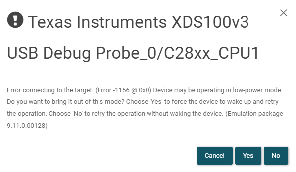
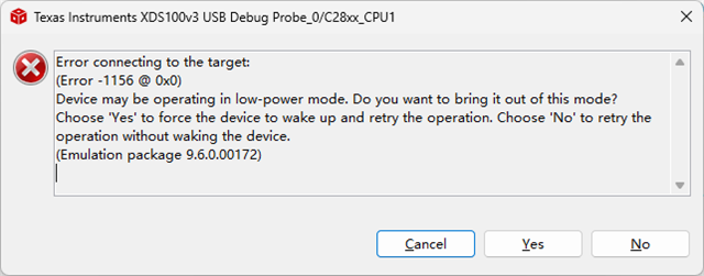
CCS尝试连接时出现如下错误:

测试了晶振工作正常,测试DSP程序控制的IO输出正常

当前不知道问题出在哪里,请帮忙分析

  • 那个帖子已经关闭了。

    现在剩下这个问题无法解决。

    没有配置DCSM时,CCS一直能够正常在线debug。

    一旦配置DCSM并下载,就出现Error -1156。将此DSP焊下来,安装到另外一种类型的控制板上,仿真器能连接并下载程序。

    下图是两种控制板的JTAG电路:

    1.下载DCSM后出问题的控制板:

    该板上JTAG经过简化,其与XDS100V3(14Pin)按下图进行连接:

    信号     CN1     xdsv100

    3.3V     1    ---   5    

    GND     2   ---   4

    空         3

    TMS     4    ---   1

    TDI       5   ---    3

    TDO     6   ---    7

    TCK      7   ---   9、11

    3.3V     8    ---   5

    2.下载DCSM后能正常在线仿真的控制板:

    图中:13、14、2脚没有与DSP连接

  • 尝试UniFlash得到如下错误提示:

  • 无法下载,但是可以正常进行"Test Connection"操作:

    [Start: Texas Instruments XDS100v3 USB Debug Probe_0]
    
    Execute the command:
    
    %ccs_base%/common/uscif/dbgjtag -f %boarddatafile% -rv -o -F inform,logfile=yes -S pathlength -S integrity
    
    [Result]
    
    
    -----[Print the board config pathname(s)]------------------------------------
    
    C:\Users\bob\AppData\Local\TEXASI~1\CCS\
        ccs1110\0\0\BrdDat\testBoard.dat
    
    -----[Print the reset-command software log-file]-----------------------------
    
    This utility has selected a 100- or 510-class product.
    This utility will load the adapter 'jioserdesusbv3.dll'.
    The library build date was 'Dec  8 2021'.
    The library build time was '11:16:32'.
    The library package version is '9.6.0.00172'.
    The library component version is '35.35.0.0'.
    The controller does not use a programmable FPGA.
    The controller has a version number of '4' (0x00000004).
    The controller has an insertion length of '0' (0x00000000).
    This utility will attempt to reset the controller.
    This utility has successfully reset the controller.
    
    -----[Print the reset-command hardware log-file]-----------------------------
    
    The scan-path will be reset by toggling the JTAG TRST signal.
    The controller is the FTDI FT2232 with USB interface.
    The link from controller to target is direct (without cable).
    The software is configured for FTDI FT2232 features.
    The controller cannot monitor the value on the EMU[0] pin.
    The controller cannot monitor the value on the EMU[1] pin.
    The controller cannot control the timing on output pins.
    The controller cannot control the timing on input pins.
    The scan-path link-delay has been set to exactly '0' (0x0000).
    
    -----[The log-file for the JTAG TCLK output generated from the PLL]----------
    
      Test  Size   Coord      MHz    Flag  Result       Description
      ~~~~  ~~~~  ~~~~~~~  ~~~~~~~~  ~~~~  ~~~~~~~~~~~  ~~~~~~~~~~~~~~~~~~~
        1     64  - 01 00  500.0kHz   O    good value   measure path length
        2     64  + 00 00  1.000MHz  [O]   good value   apply explicit tclk
    
    There is no hardware for measuring the JTAG TCLK frequency.
    
    In the scan-path tests:
    The test length was 2048 bits.
    The JTAG IR length was 6 bits.
    The JTAG DR length was 1 bits.
    
    The IR/DR scan-path tests used 2 frequencies.
    The IR/DR scan-path tests used 500.0kHz as the initial frequency.
    The IR/DR scan-path tests used 1.000MHz as the highest frequency.
    The IR/DR scan-path tests used 1.000MHz as the final frequency.
    
    -----[Measure the source and frequency of the final JTAG TCLKR input]--------
    
    There is no hardware for measuring the JTAG TCLK frequency.
    
    -----[Perform the standard path-length test on the JTAG IR and DR]-----------
    
    This path-length test uses blocks of 64 32-bit words.
    
    The test for the JTAG IR instruction path-length succeeded.
    The JTAG IR instruction path-length is 6 bits.
    
    The test for the JTAG DR bypass path-length succeeded.
    The JTAG DR bypass path-length is 1 bits.
    
    -----[Perform the Integrity scan-test on the JTAG IR]------------------------
    
    This test will use blocks of 64 32-bit words.
    This test will be applied just once.
    
    Do a test using 0xFFFFFFFF.
    Scan tests: 1, skipped: 0, failed: 0
    Do a test using 0x00000000.
    Scan tests: 2, skipped: 0, failed: 0
    Do a test using 0xFE03E0E2.
    Scan tests: 3, skipped: 0, failed: 0
    Do a test using 0x01FC1F1D.
    Scan tests: 4, skipped: 0, failed: 0
    Do a test using 0x5533CCAA.
    Scan tests: 5, skipped: 0, failed: 0
    Do a test using 0xAACC3355.
    Scan tests: 6, skipped: 0, failed: 0
    All of the values were scanned correctly.
    
    The JTAG IR Integrity scan-test has succeeded.
    
    -----[Perform the Integrity scan-test on the JTAG DR]------------------------
    
    This test will use blocks of 64 32-bit words.
    This test will be applied just once.
    
    Do a test using 0xFFFFFFFF.
    Scan tests: 1, skipped: 0, failed: 0
    Do a test using 0x00000000.
    Scan tests: 2, skipped: 0, failed: 0
    Do a test using 0xFE03E0E2.
    Scan tests: 3, skipped: 0, failed: 0
    Do a test using 0x01FC1F1D.
    Scan tests: 4, skipped: 0, failed: 0
    Do a test using 0x5533CCAA.
    Scan tests: 5, skipped: 0, failed: 0
    Do a test using 0xAACC3355.
    Scan tests: 6, skipped: 0, failed: 0
    All of the values were scanned correctly.
    
    The JTAG DR Integrity scan-test has succeeded.
    
    [End: Texas Instruments XDS100v3 USB Debug Probe_0]

  • 重新找了一块全新的DSP,按以下步骤测试:
    1。能正常下载和Debug未配置DCSM的程序,断电后程序正常运行,CCS可以再次下载和Debug,
    2.第1次加密,使用简单密码,Zone1.PSWD3=0x12345678,Zone2.PSWD3=0x87654321,其他密码字段采用默认值,下载后程序正常运行,断电后程序正常运行,CCS可以再次下载和Debug(CCS中需设置密码),
    3.第2次加密,使用重复简单密码,
    Zone1.PSWD0=Zone1.PSWD2=Zone1.PSWD3=0x12345678,Zone1.PSWD1=Default
    Zone2.PSWD0=Zone2.PSWD2=Zone2.PSWD3=0x87654321,Zone2.PSWD1=Default
    下载后,断电,程序正常运行,再次尝试Debug,出现 Error -1156,low-power提示
  • 参照

    https://e2echina.ti.com/support/microcontrollers/c2000/f/c2000-microcontrollers-forum/757377/tms320f280025-dcsm-280025-flash-jtag-uniflash

    配置了DCSM的DSP,上电后需要进入Wait模式才可以正常在线调试

    控制板GPIO32和GPIO24都是拉高的状态,强制将GPIO24拉低后,可以正常下载调试了

  • 好的,感谢分享!

    一下子没有想起来这部分的内容,配置了DCSM以后再进行仿真程序会陷入ECSL,需要执行ECSL PMF流程;这时需要将器件配置为wait boot mode,程序就不会向被保护的用户代码跳转,也就不会陷入ECSL逻辑,否则就会中断仿真连接;接着执行PMF流程就可以成功仿真:

    sprui33f_TMS320F28004x Real-Time Microcontrollers Technical Reference Manual (Rev. F)1373.13.1.2 Emulation Code Security Logic (ECSL)