This thread has been locked.

If you have a related question, please click the "Ask a related question" button in the top right corner. The newly created question will be automatically linked to this question.

TMS320F28377S: 主从机两个DSP CAN通信问题求助

Part Number: TMS320F28377S

问题描述:。

主从机均为TMS320F28377S,通过CAN通信交互数据,波特率500kHz。

主机每1ms发送一帧数据给从机,长度5个字节。

从机采用中断方式接收主机数据,开始一段时间接收正常,过一段时间后,从机接收不到主机的数据,间隔时间不固定,有时很长时间也没有接收不到的现象。

另:从机接收不到主机数据现象发生后,通过Can工具给从机DSP发送其他帧ID数据,从机还能成功接收。

请问:

该现象是怎么产生的?应该如何解决呢?

  • 有单步调过吗?主从机的程序分别停在哪里?

  • 没有,逆变器跑的大功率。主机的数据还在发送,通过CANTest工具可以看到,从机接收不到了。

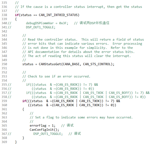
  •  从机接收不到主机的数据时,从机程序也没进入上面CAN通信错误中断中。会是因为我程序还有个1ms中断,把CAN接收中断影响了吗?

  • 总结一下就是,异常发生时,主机还可以发送该帧ID的数据,从机还可以接收其它帧ID的数据。

    另:从机接收不到主机数据现象发生后,通过Can工具给从机DSP发送其他帧ID数据,从机还能成功接收。

    如果用Can工具给从机发送该帧ID的数据,从机能接收到吗?

    会是因为我程序还有个1ms中断,把CAN接收中断影响了吗?

    这个是什么中断?

  • (1)如果用Can工具给从机发送该帧ID的数据,从机能接收到吗?

    ==== 从机也接收不到。

    (2)这个是什么中断?

    ==== 这个是定时器中断,用来处理其他任务的,1ms中断中程序的执行时间测试最长有70us。

  • 有检查过中间的连接正常吗?

    可以分享下can的配置吗?

  • (1)有检查过中间的连接正常吗?

    ==== 中间连接是正常的。

    (2)can的相关配置如下:

    // ====================================================================
    // === 1. 主函数初始化部分 ============================================
    // ====================================================================
    void main(void)
    {
        //
        // Initialize the CAN controllers
        //
        CANInit(CANA_BASE);
    
        //
        // Setup CAN to be clocked off the PLL output clock
        //
        CANClkSourceSelect(CANA_BASE, 0);
    
        //
        // Set up the CAN bus bit rate to 500kHz for each module
        // This function sets up the CAN bus timing for a nominal configuration.
        // You can achieve more control over the CAN bus timing by using the
        // function CANBitTimingSet() instead of this one, if needed.
        // Additionally, consult the device data sheet for more information about
        // the CAN module clocking.
        //
        CANBitRateSet(CANA_BASE, 200000000, 500000);
    //    CANBitRateSet(CANA_BASE, 200000000, 1000000);
    
        //
        // Enable interrupts on the CAN A peripheral.
        //
    //    CANIntEnable(CANA_BASE, CAN_INT_MASTER | CAN_INT_ERROR | CAN_INT_STATUS);
        CANIntEnable(CANA_BASE, CAN_INT_MASTER | CAN_INT_ERROR);
    
        // Enable AutoBusOn
        CAN_enableAutoBusOn(CANA_BASE);
        CAN_setAutoBusOnTime(CANA_BASE, 100000);
        CAN_disableRetry(CANA_BASE);
        //
        // Enable the CAN-A interrupt signal
        //
        CANGlobalIntEnable(CANA_BASE, CAN_GLB_INT_CANINT0);
    
        CanObjInit();
    
        //
        // Start CAN module A operations
        //
        CANEnable(CANA_BASE);
    }
    
    // ====================================================================
    // === 2. 主机DSP CanObjInit()初始化配置邮箱,及发送程序  =============
    // ====================================================================
    void CanObjInit()
    {
        // 两DSP CAN通信,发送
        sTXCANMsgDspComm01.ui32MsgID = 0x0C100201;
        sTXCANMsgDspComm01.ui32MsgIDMask = 0;
        sTXCANMsgDspComm01.ui32Flags = 0;
        sTXCANMsgDspComm01.ui32MsgLen = 5;
        sTXCANMsgDspComm01.pucMsgData = TxMsgDspCommData01;
    }
    
    
    // ====== 发送部分程序,1ms发送1次 =====================================
        // 发送给从机电流设定值
        TxMsgDspCommData01[0] = ((int)(onGridCloseLoopIdref * 100) & 0x00FF);
        TxMsgDspCommData01[1] = ((int)(onGridCloseLoopIdref * 100) & 0xFF00) >> 8;
        TxMsgDspCommData01[2] = ((int)(onGridCloseLoopIqref * 100) & 0x00FF);
        TxMsgDspCommData01[3] = ((int)(onGridCloseLoopIqref * 100) & 0xFF00) >> 8;
        TxMsgDspCommData01[4] = 0;
        CANMessageSet(CANA_BASE, 4, &sTXCANMsgDspComm01, MSG_OBJ_TYPE_TX);
    
    // ====================================================================
    // === 3. 从机DSP CanObjInit()初始化配置邮箱,及接收程序  =============
    // ====================================================================
    void CanObjInit()
    {
        // 两DSP CAN通信,接收
        sRXCANMsgDspComm01.ui32MsgID = 0x0C100201;
        sRXCANMsgDspComm01.ui32MsgIDMask = 0;
        sRXCANMsgDspComm01.ui32Flags = MSG_OBJ_RX_INT_ENABLE;
        sRXCANMsgDspComm01.ui32MsgLen = 5;
        sRXCANMsgDspComm01.pucMsgData = RxMsgDspCommData01;
        CANMessageSet(CANA_BASE, 15, &sRXCANMsgDspComm01, MSG_OBJ_TYPE_RX);
    }
    
    // ======== 在中断中接收主机发送过来的数据(status = 15时接收该帧  ) ============================
    #if (G9_5PL != 0)
    __interrupt void CANA0_ISR(void)    // CAN-A
    {
        // Set interrupt priority:
        volatile Uint16 TempPIEIER = PieCtrlRegs.PIEIER9.all;
        IER |= M_INT9;
        IER    &= MINT9;                         // Set "global" priority
        PieCtrlRegs.PIEIER9.all &= MG9_5;   // Set "group"  priority
        PieCtrlRegs.PIEACK.all = 0xFFFF;   // Enable PIE interrupts
        __asm("  NOP");
        EINT;
    
        uint32_t status;
    
        //
        // Read the CAN-A interrupt status to find the cause of the interrupt
        //
        status = CANIntStatus(CANA_BASE, CAN_INT_STS_CAUSE);
    
        //
        // If the cause is a controller status interrupt, then get the status
        //
        if(status == CAN_INT_INT0ID_STATUS)
        {
    //        DSP_OUT1_TOGGLE;
    
            //
            // Read the controller status.  This will return a field of status
            // error bits that can indicate various errors.  Error processing
            // is not done in this example for simplicity.  Refer to the
            // API documentation for details about the error status bits.
            // The act of reading this status will clear the interrupt.
            //
            status = CANStatusGet(CANA_BASE, CAN_STS_CONTROL);
    
            //
            // Check to see if an error occurred.
            //
    //        if(((status  & ~(CAN_ES_RXOK)) != 7) &&
    //           ((status  & ~(CAN_ES_RXOK)) != 0))
    //        if(((status  & ~(CAN_ES_RXOK | CAN_ES_TXOK | CAN_ES_BOFF)) != 7) &&
    //           ((status  & ~(CAN_ES_RXOK | CAN_ES_TXOK | CAN_ES_BOFF)) != 0))
            if(((status  & ~(CAN_ES_RXOK | CAN_ES_TXOK)) != 7) &&
               ((status  & ~(CAN_ES_RXOK | CAN_ES_TXOK)) != 0))
            {
                //
                // Set a flag to indicate some errors may have occurred.
                //
                errorFlag = 1;   // 调试
                CanConfigInit();
    //            DSP_OUT1_TOGGLE;   // 调试
            }
        }
        else if(status == 15)
        {
            DSP_OUT1_TOGGLE;
    
            errorFlag = 0;
            CanReceiveDsp01();
    
            CANIntClear(CANA_BASE, 15);
        }
        else if(status == 16)
        {
            CanReceiveDsp02();
    
            CANIntClear(CANA_BASE, 16);
        }
        else if(status == 17)
        {
    //        DSP_OUT1_TOGGLE;   // 调试
    
            CanReceiveDsp03();
    
            CANIntClear(CANA_BASE, 17);
        }
        //
        // Check if the cause is the CAN-A receive message object 1
        //
        else if(status == 25)
        {
            //
            // Get the received message
            //
    //        CANMessageGet(CANA_BASE, 2, &sRXCANMsgChkInfo, true);
    
            CanReceiveSrhInfo();
    
            //
            // Getting to this point means that the RX interrupt occurred on
            // message object 1, and the message RX is complete.  Clear the
            // message object interrupt.
            //
            CANIntClear(CANA_BASE, 25);
    
            //
            // Increment a counter to keep track of how many messages have been
            // received. In a real application this could be used to set flags to
            // indicate when a message is received.
            //
    //        rxMsgCount++;
    
            //
            // Since the message was received, clear any error flags.
            //
    //        errorFlag = 0;
        }
        else if(status == 26)
        {
            CanReceiveRdSet();
    
            CANIntClear(CANA_BASE, 26);
        }
        else if(status == 27)
        {
            CanReceiveCtlSet();
    
            CANIntClear(CANA_BASE, 27);
        }
        else if(status == 28)
        {
            CanReceiveParaSet();
    
            CANIntClear(CANA_BASE, 28);
        }
    
        //
        // If something unexpected caused the interrupt, this would handle it.
        //
        else
        {
            //
            // Spurious interrupt handling can go here.
            //
    //        errorFlag = 2;   // 调试
        }
    
        //
        // Clear the global interrupt flag for the CAN interrupt line
        //
        CANGlobalIntClear(CANA_BASE, CAN_GLB_INT_CANINT0);
    
    
        //
        // Restore registers saved:
        //
        DINT;
        PieCtrlRegs.PIEIER9.all = TempPIEIER;
    }
    #endif

  • What could be happening is that the interrupts are not being serviced promptly leading to the impression that messages are being lost.

    ===== 什么会导致中断程序没有被及时服务呢?

    If masking is not used and the message object is retaining the correct MSGID (ARBID), it will receive a transmitted message. It cannot suddenly stop receiving messages.

    ===== 程序中掩码没有用,MSGID (ARBID)也没有更改。

    怎么去进一步定位到问题呢?

  • 好的,我跟进过去了

  • 麻烦再帮忙问一下:

    If a message was indeed over-written (because it was not read in time by the software), this bit would be set.

    ===== 消息被重写丢失后,出错的消息对象会一直收不到数据吗?

    The application could either configure more message objects for receive or otherwise ensure that CAN interrupts are serviced on time.

    ===== 我可以使用两个不同的消息对象接收同一个ID的数据吗?

    谢谢!

  • No, the fact that a message was overwritten before being read should not prevent that message object from receiving future messages.

    Only if the message objects are part of a FIFO. 

    ===== 我现在是出问题的消息对象再也接收不到消息了。我能通过配置成FIFO接收模式解决吗?如果可以的话,麻烦给下配置成FIFO接收模式的例程。谢谢。

  • Please have customer check the MsgLst (Receive Message Lost) bit for the suspected message object. If a message was indeed over-written (because it was not read in time by the software), this bit would be set. 

    ===== 我按以下方法检查MsgLst位,发现从机接收不到主机数据时,从机出错消息对象的MsgLst没有被置位。

    if( (sRXCANMsgDspComm05.ui32Flags & MSG_OBJ_DATA_LOST) == 1)
    {
    systemFault.bit.DebugFault = 1;    // Send to the upper computer for observation
    }

    我还能做哪些调试?

  • 感觉这个CAN内核只从早期F280x、F2803x改进后问题不少,我在F280025上遇到不使能Mask,MaskID全设为0的情况下都只能接收到邮箱预设ID(通过SysCfg配置)的数据帧,其他ID的数据帧无法接收到。感觉还是原来那种消息RAM直接映射的方式比较好,连上仿真器每个邮箱的设置和状态一目了然。

  • 你描述的是正常的吧。是要使能Mask,MaskID全设为0,这个邮箱才能接收到所有帧的数据吧。

  • 使能Mask后MID中 bit=1需要匹配,bit=0 don‘t care,

    不使能Mask不是应该接收所有帧吗?我理解错了??

  • “使能Mask后MID中 bit=1需要匹配,bit=0 don‘t care。”

    ===== 这个我理解是对的。

    不使能Mask就要完全匹配帧ID才能接收。使能了Mask,设置的MaskID才有用。你可以试试。

  • OK,我试试。找到了文档里面相关部分(下图),既然UMask=0不再过滤,一般理解应该是接收所有消息才对。

  • 这个函数的注释。

  • 好的,跟进过去了~

  • 已经解决了,需要设置UMask=1以及Msk ID=0才能接收所有数据帧

  • 问题解决就好~也感谢分享解决方案