/*
 * main.c
 *
 *  Created on: 2023年9月14日
 *      Author: CHENJIE
 */
#include "RFFT.h"
#include "epwm.h"
#include "DSP2833x_Device.h"
#include "DSP2833x_Examples.h"
#include "adc.h"
#include "epwm.h"
#include "stdio.h"
#include "uart.h"
#include "dma.h"
#include "leds.h"


__interrupt void adc_isr(void);
__interrupt void ocal_DINTCH1_ISR(void);

float freq;
Uint16 array_index;
Uint16 check_flag;
Uint16 LoopCount;
Uint16 ConversionCount;

//#pragma DATA_SECTION(DMABuf1,"DMARAML4");

//#define DMA_BUF_SIZE 60
//volatile Uint16 DMABuf1[DMA_BUF_SIZE];

#pragma DATA_SECTION(Voltage1, "DMARAML4");

Uint16 Voltage1[2048];


volatile Uint16 *DMADest;
volatile Uint16 *DMASource;


void main()
{
    check_flag=0;
    //
    // Step 1. Initialize System Control:
    // PLL, WatchDog, enable Peripheral Clocks
    // This example function is found in the DSP2833x_SysCtrl.c file.
    //
    InitSysCtrl();


//    MemCopy(&RamfuncsLoadStart,&RamfuncsLoadEnd,&RamfuncsRunStart);
//    InitFlash();

    EALLOW;
    #if (CPU_FRQ_150MHZ)     // Default - 150 MHz SYSCLKOUT
        //
        // HSPCLK = SYSCLKOUT/2*ADC_MODCLK2 = 150/(2*3)   = 25.0 MHz
        //
        #define ADC_MODCLK 0x3
    #endif
    #if (CPU_FRQ_100MHZ)
        //
        // HSPCLK = SYSCLKOUT/2*ADC_MODCLK2 = 100/(2*2)   = 25.0 MHz
        //
        #define ADC_MODCLK 0x2
    #endif
    EDIS;

    //
    // Define ADCCLK clock frequency ( less than or equal to 25 MHz )
    // Assuming InitSysCtrl() has set SYSCLKOUT to 150 MHz
    //
    EALLOW;
    SysCtrlRegs.HISPCP.all = ADC_MODCLK;
    EDIS;

    //
    // Step 2. Initialize GPIO:
    // This example function is found in the DSP2833x_Gpio.c file and
    // illustrates how to set the GPIO to it's default state.
    //
    // InitGpio();  // Skipped for this example

    //
    // Step 3. Clear all interrupts and initialize PIE vector table:
    // Disable CPU interrupts
    //
    DINT;

    //
    // Initialize the PIE control registers to their default state.
    // The default state is all PIE interrupts disabled and flags
    // are cleared.
    // This function is found in the DSP2833x_PieCtrl.c file.
    //
    InitPieCtrl();

    //
    // Disable CPU interrupts and clear all CPU interrupt flags:
    //
    IER = 0x0000;
    IFR = 0x0000;

    //
    // Initialize the PIE vector table with pointers to the shell Interrupt
    // Service Routines (ISR).
    // This will populate the entire table, even if the interrupt
    // is not used in this example.  This is useful for debug purposes.
    // The shell ISR routines are found in DSP2833x_DefaultIsr.c.
    // This function is found in DSP2833x_PieVect.c.
    //
    InitPieVectTable();

    //
    // Interrupts that are used in this example are re-mapped to
    // ISR functions found within this file.
    //
//    EALLOW;  // This is needed to write to EALLOW protected register
//    PieVectTable.ADCINT = &adc_isr;
//    EDIS;    // This is needed to disable write to EALLOW protected registers

    EALLOW; // Allow access to EALLOW protected registers
    PieVectTable.DINTCH1= &local_DINTCH1_ISR;
    EDIS;   // Disable access to EALLOW protected registers

    PieCtrlRegs.PIEIER1.bit.INTx1 = 1;
    IER |= M_INT7;      // Enable CPU Interrupt 1
    //
    // Step 4. Initialize all the Device Peripherals:
    // This function is found in DSP2833x_InitPeripherals.c
    //
    // InitPeripherals(); // Not required for this example
    InitAdc();  // For this example, init the ADC

    //
    // Step 5. User specific code, enable interrupts:
    //

    //
    // Enable ADCINT in PIE
    //
//    PieCtrlRegs.PIEIER1.bit.INTx6 = 1;
//    IER |= M_INT1;      // Enable CPU Interrupt 1

    EINT;               // Enable Global interrupt INTM
    //ERTM;               // Enable Global realtime interrupt DBGM

    LoopCount = 0;
    ConversionCount = 0;

    //
    // Configure ADC
    //
    AdcRegs.ADCTRL1.bit.ACQ_PS = 0Xf;
    AdcRegs.ADCTRL3.bit.ADCCLKPS = 0x0; //不对高速时钟分频
    AdcRegs.ADCTRL1.bit.CONT_RUN = 0;     // Setup continuous run
    AdcRegs.ADCMAXCONV.all = 0x0000;       // Setup 2 conv's on SEQ1
    AdcRegs.ADCCHSELSEQ1.bit.CONV00 = 0x0; // Setup ADCINA3 as 1st SEQ1 conv.


    //
    // Enable SOCA from ePWM to start SEQ1
    //
    AdcRegs.ADCTRL2.bit.EPWM_SOCA_SEQ1 = 1;

    AdcRegs.ADCTRL2.bit.INT_ENA_SEQ1 = 1;  // Enable SEQ1 interrupt (every EOS)

    //
    // Assumes ePWM1 clock is already enabled in InitSysCtrl();
    //
    EPwm1Regs.ETSEL.bit.SOCAEN = 1;     // Enable SOC on A group
    EPwm1Regs.ETSEL.bit.SOCASEL = 4;    // Select SOC from from CPMA on upcount
    EPwm1Regs.ETPS.bit.SOCAPRD = 1;     // Generate pulse on 1st event
    EPwm1Regs.CMPA.half.CMPA = 20;   // Set compare A value
    EPwm1Regs.TBPRD = 75-1;           // Set period for ePWM1
    EPwm1Regs.TBCTL.bit.CTRMODE = 0;    // count up and start

    EALLOW;
    SysCtrlRegs.PCLKCR3.bit.DMAENCLK = 1;       // DMA Clock
    EDIS;
    // Initialize DMA
    DMAInitialize();

    // Configure DMA Channel

    DMADest=&Voltage1[0];
    DMASource=&AdcMirror.ADCRESULT0;
    DMACH1AddrConfig(DMADest,DMASource);

    DMACH1BurstConfig(31,0,2);

       //
       // so need to increment by 2 to grab the correct location
       //
       DMACH1TransferConfig(31,0,2);
       DMACH1WrapConfig(0xFFFF,0,0xFFFF,0);
    //Use timer0 to start the x-fer.
    //Since this is a static copy use one shot mode, so only one trigger is needed
    //Also using 32-bit mode to decrease x-fer time
    DMACH1ModeConfig(DMA_SEQ1INT,PERINT_ENABLE,ONESHOT_DISABLE,CONT_ENABLE,SYNC_DISABLE,
                     SYNC_DST,OVRFLOW_DISABLE,THIRTYTWO_BIT,CHINT_END,CHINT_ENABLE);

    StartDMACH1();
 //
    // Wait for ADC interrupt
    //
    for(;;)
    {

        if(check_flag==1)
        {

          RFFT_ADC_Init(Voltage1);
          RFFT_ADC_Caculate();

          EPwm1Regs.ETSEL.bit.SOCAEN = 1;
          StartDMACH1();

          check_flag=0;

        }
    }
}

//
// adc_isr -
//
__interrupt void
local_DINTCH1_ISR(void)
{

//
//    EALLOW;
//     SysCtrlRegs.PCLKCR3.bit.DMAENCLK = 0;       // DMA Clock
//     EDIS;


//    Voltage1[ConversionCount] = AdcRegs.ADCRESULT0 >>4;
//
//    //
//    // If 40 conversions have been logged, start over
//    //
//    if(ConversionCount > 2048)
//    {
//
//        ConversionCount = 0;
//        EPwm1Regs.ETSEL.bit.SOCAEN = 0;     // Enable SOC on A group
//        check_flag=1;
//
//    }
//    else
//    {
//        ConversionCount++;
//    }
//
//    //
//    // Reinitialize for next ADC sequence
//    //
    EPwm1Regs.ETSEL.bit.SOCAEN = 0;     // Enable SOC on A group
    AdcRegs.ADCTRL2.bit.RST_SEQ1 = 1;         // Reset SEQ1
    AdcRegs.ADCST.bit.INT_SEQ1_CLR = 1;       // Clear INT SEQ1 bit
    PieCtrlRegs.PIEACK.all = PIEACK_GROUP1;   // Acknowledge interrupt to PIE
//
//    return;

      check_flag=1;

    PieCtrlRegs.PIEACK.bit.ACK7 = 1;


}
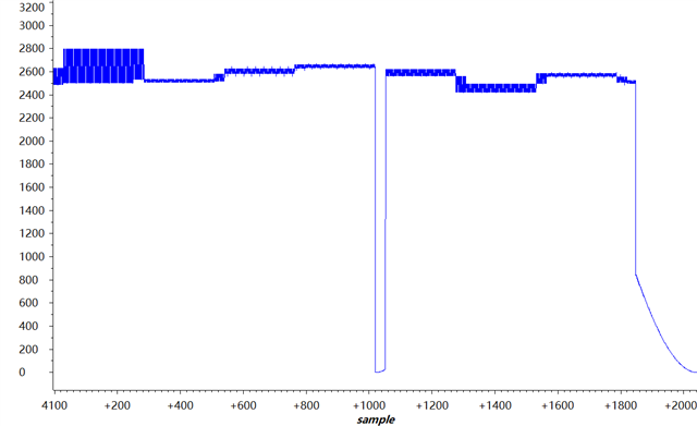
使用epwm触发adc采样,dma传输时数据异常