Part Number: TMS320F280049C
Other Parts Discussed in Thread: LAUNCHXL-F280049C,
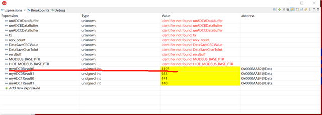
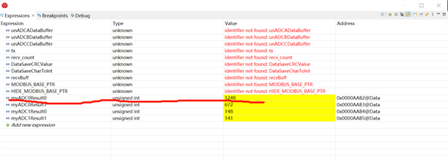
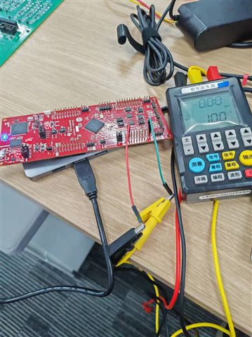
使用官方的LAUNCHXL-F280049C开发板,跑adc_ex1_soc_software例程验证ADC采样的问题顶,我在while(1)循环中把最后的ESTOP0屏蔽,然后在线调试,观察myADC0Result0的数值变化,给开发板的A0通道接入了信号源,给1V,发现转换结果在1200-1300之间跳变,数据很不准确,想问下是什么原因?