

Part Number: TMS320F28384D
Other Parts Discussed in Thread: SYSCONFIG
I hope this email finds you well.
I am currently working on a project involving the CAN peripheral on the 28384D microcontroller. I have encountered an issue where I am unable to use the CAN interrupt functionality. However, the CAN peripheral works fine when I use polling.
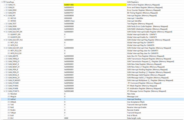
To help diagnose the problem, I am providing the relevant configuration details from SysConfig and the runtime register values below: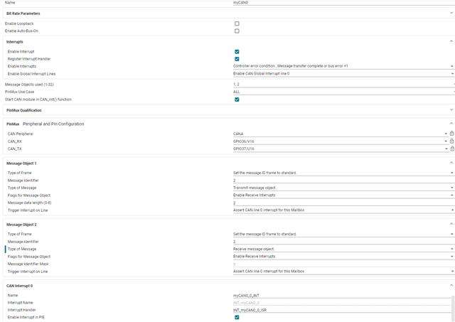
//#############################################################################
//
// FILE:   can_ex1_loopback.c
//
// TITLE:   CAN External Loopback Example
//
//! \addtogroup driver_example_list
//! <h1> CAN External Loopback </h1>
//!
//! This example shows the basic setup of CAN in order to transmit and receive
//! messages on the CAN bus.  The CAN peripheral is configured to transmit
//! messages with a specific CAN ID.  A message is then transmitted once per
//! second, using a simple delay loop for timing.  The message that is sent is
//! a 2 byte message that contains an incrementing pattern.
//!
//! This example sets up the CAN controller in External Loopback test mode.
//! Data transmitted is visible on the CANTXA pin and is received internally
//! back to the CAN Core. Please refer to details of the External Loopback
//! Test Mode in the CAN Chapter in the Technical Reference Manual. Refer
//! to [Programming Examples and Debug Strategies for
//! the DCAN Module](www.ti.com/lit/SPRACE5) for useful information about
//! this example
//!
//! \b External \b Connections \n
//!  - None.
//!
//! \b Watch \b Variables \n
//!  - msgCount - A counter for the number of successful messages received
//!  - txMsgData - An array with the data being sent
//!  - rxMsgData - An array with the data that was received
//!
//
//#############################################################################
//
//
//
// C2000Ware v5.03.00.00
//
// Copyright (C) 2024 Texas Instruments Incorporated - http://www.ti.com
//
// Redistribution and use in source and binary forms, with or without
// modification, are permitted provided that the following conditions
// are met:
//
//   Redistributions of source code must retain the above copyright
//   notice, this list of conditions and the following disclaimer.
//
//   Redistributions in binary form must reproduce the above copyright
//   notice, this list of conditions and the following disclaimer in the
//   documentation and/or other materials provided with the
//   distribution.
//
//   Neither the name of Texas Instruments Incorporated nor the names of
//   its contributors may be used to endorse or promote products derived
//   from this software without specific prior written permission.
//
// THIS SOFTWARE IS PROVIDED BY THE COPYRIGHT HOLDERS AND CONTRIBUTORS
// "AS IS" AND ANY EXPRESS OR IMPLIED WARRANTIES, INCLUDING, BUT NOT
// LIMITED TO, THE IMPLIED WARRANTIES OF MERCHANTABILITY AND FITNESS FOR
// A PARTICULAR PURPOSE ARE DISCLAIMED. IN NO EVENT SHALL THE COPYRIGHT
// OWNER OR CONTRIBUTORS BE LIABLE FOR ANY DIRECT, INDIRECT, INCIDENTAL,
// SPECIAL, EXEMPLARY, OR CONSEQUENTIAL DAMAGES (INCLUDING, BUT NOT
// LIMITED TO, PROCUREMENT OF SUBSTITUTE GOODS OR SERVICES; LOSS OF USE,
// DATA, OR PROFITS; OR BUSINESS INTERRUPTION) HOWEVER CAUSED AND ON ANY
// THEORY OF LIABILITY, WHETHER IN CONTRACT, STRICT LIABILITY, OR TORT
// (INCLUDING NEGLIGENCE OR OTHERWISE) ARISING IN ANY WAY OUT OF THE USE
// OF THIS SOFTWARE, EVEN IF ADVISED OF THE POSSIBILITY OF SUCH DAMAGE.
// $
//#############################################################################

//
// Included Files
//
#include "driverlib.h"
#include "device.h"
#include "board.h"

//
// Defines
//
#define MSG_DATA_LENGTH    2
#define TX_MSG_OBJ_ID    1
#define RX_MSG_OBJ_ID    2

//
// Globals
//
volatile unsigned long msgCount = 0;
uint16_t txMsgData[2], rxMsgData[2];
uint16_t errorFlag = 0;
uint16_t rxMsgCount = 0;
//
// Main
//
void main(void)
{
    uint16_t txMsgData[2], rxMsgData[2];

    //
    // Initialize device clock and peripherals
    //
    Device_init();

    //
    // Initialize GPIO and configure GPIO pins for CANTX/CANRX
    //
    Device_initGPIO();

    //
    // Allocated shared peripheral to C28x
    //
    SysCtl_allocateSharedPeripheral(SYSCTL_PALLOCATE_CAN_A,0x0U);
    SysCtl_allocateSharedPeripheral(SYSCTL_PALLOCATE_CAN_B,0x0U);

    //
    // Board initialization
    //
    Board_init();

    //
    // Initialize PIE and clear PIE registers. Disables CPU interrupts.
    //
    Interrupt_initModule();

    //
    // Initialize the PIE vector table with pointers to the shell Interrupt
    // Service Routines (ISR).
    //
    Interrupt_initVectorTable();

    //
    // Enable Global Interrupt (INTM) and realtime interrupt (DBGM)
    //
    EINT;
    ERTM;

    //
    // Setup send and receive buffers
    //
    txMsgData[0] = 0x01;
    txMsgData[1] = 0x02;
    *(uint16_t *)rxMsgData = 0;

    GPIO_togglePin(myBoardLED0_GPIO);
    DEVICE_DELAY_US(500000);
    GPIO_togglePin(myBoardLED0_GPIO);
    GPIO_togglePin(myBoardLED1_GPIO);
    DEVICE_DELAY_US(500000);
    GPIO_togglePin(myBoardLED1_GPIO);
    //
    // Loop Forever - Send and Receive data continuously
    //
    for(;;)
    {
        //
        // Send CAN message data from message object 1
        //
        /*
        CAN_sendMessage(myCAN0_BASE, 1, MSG_DATA_LENGTH, txMsgData);

        CAN_readMessage(myCAN0_BASE, RX_MSG_OBJ_ID, rxMsgData);
                SCI_writeCharNonBlocking(mySCI0_BASE, rxMsgData[0]);
                DEVICE_DELAY_US(500000);
        */
    }
}
__interrupt void INT_myCAN0_0_ISR(void)
{
    uint32_t status;
    GPIO_togglePin(myBoardLED0_GPIO);
        //
        // Read the CAN-B interrupt status to find the cause of the interrupt
        //
        status = CAN_getInterruptCause(myCAN0_BASE);
        //SCI_writeCharNonBlocking(mySCI0_BASE, status);

        //
        // If the cause is a controller status interrupt, then get the status
        //
        /*if(status == CAN_INT_INT0ID_STATUS)
        {
            //
            // Read the controller status.  This will return a field of status
            // error bits that can indicate various errors.  Error processing
            // is not done in this example for simplicity.  Refer to the
            // API documentation for details about the error status bits.
            // The act of reading this status will clear the interrupt.
            //
            status = CAN_getStatus(myCAN0_BASE);


            //
            // Check to see if an error occurred.
            //
            if(((status  & ~(CAN_STATUS_RXOK)) != CAN_STATUS_LEC_MSK) &&
               ((status  & ~(CAN_STATUS_RXOK)) != CAN_STATUS_LEC_NONE))
            {
                //
                // Set a flag to indicate some errors may have occurred.
                //
                errorFlag = 1;
            }
            //GPIO_togglePin(myBoardLED1_GPIO);
        }*/
        //
        // Check if the cause is the CAN receive message object 1
        //
        if(status == RX_MSG_OBJ_ID)
        {
            //
            // Get the received message
            //
            GPIO_togglePin(myBoardLED1_GPIO);
            CAN_readMessage(myCAN0_BASE, RX_MSG_OBJ_ID, rxMsgData);

            //
            // Getting to this point means that the RX interrupt occurred on
            // message object 1, and the message RX is complete.  Clear the
            // message object interrupt.
            //
            CAN_clearInterruptStatus(myCAN0_BASE, RX_MSG_OBJ_ID);

            //
            // Increment a counter to keep track of how many messages have been
            // received. In a real application this could be used to set flags to
            // indicate when a message is received.
            //
            rxMsgCount++;
            errorFlag = 0;
            //GPIO_writePin(myBoardLED0_GPIO, tag);
            SCI_writeCharNonBlocking(mySCI0_BASE, rxMsgData[0]);
            CAN_sendMessage(myCAN0_BASE, TX_MSG_OBJ_ID, MSG_DATA_LENGTH, rxMsgData);
            //
            // Since the message was received, clear any error flags.
            //

        }
        //
        // If something unexpected caused the interrupt, this would handle it.
        //
        else
        {
            //
            // Spurious interrupt handling can go here.
            //
        }

        //
        // Clear the global interrupt flag for the CAN interrupt line
        //
        // SCI_writeCharNonBlocking(mySCI0_BASE, tag);
        CAN_clearGlobalInterruptStatus(myCAN0_BASE, CAN_GLOBAL_INT_CANINT0);

        //
        // Acknowledge this interrupt located in group 9
        //
        Interrupt_clearACKGroup(INTERRUPT_ACK_GROUP9);

}
__interrupt void INT_myCAN0_1_ISR(void)
{

}


//
// End of File
//
