

Part Number: TMS320F28377D
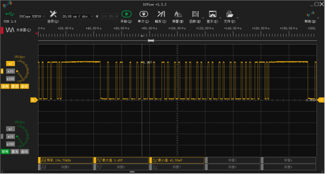
如题,下图是开发板TX与地的波形
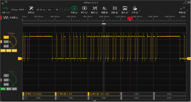
开发板的RX与地
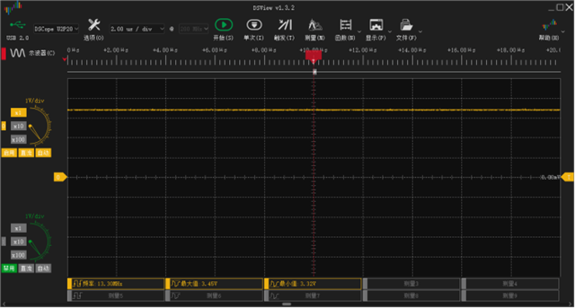
下图为我自己的板子TX与地
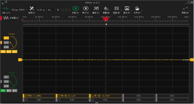
RX与地
下面为代码,上面的是开发板的,下面注释的是我自己板子的,区别仅仅是一个使用CANA一个使用CANB,请问可能是什么原因呢?
//#############################################################################
//
// FILE:   can_ex2_loopback_interrupts.c
//
// TITLE:   CAN External Loopback with Interrupts Example
//
//! \addtogroup driver_example_list
//! <h1> CAN External Loopback with Interrupts </h1>
//!
/*  这段代码实现了CAN总线的外部回环测试(External Loopback),通过中断机制实现数据的自发自收。主要功能:

    初始化CAN模块,配置为外部回环模式(数据从TXpin发出后,内部直接回到RX端:TX->TXpin->RX)。

    配置两个消息对象(邮箱):一个用于发送数据(TX),一个用于接收数据(RX)。

    每秒发送一次递增数据,通过中断确认发送完成和接收数据。

    统计发送和接收的消息数量,并检查错误。
 */
//! This example shows the basic setup of CAN in order to transmit and receive
//! messages on the CAN bus.  The CAN peripheral is configured to transmit
//! messages with a specific CAN ID.  A message is then transmitted once per
//! second, using a simple delay loop for timing.  The message that is sent is
//! a 4 byte message that contains an incrementing pattern.  A CAN interrupt
//! handler is used to confirm message transmission and count the number of
//! messages that have been sent.
//!
//! This example sets up the CAN controller in External Loopback test mode.
//! Data transmitted is visible on the CANTXA pin and is received internally
//! back to the CAN Core. CAN-B module is not involved.
//!
//! Note: "External" loopback does not mean the loopback is done externally.
//! The loopback is done internally, but the transmitted data can be seen
//! externally on the CANTX pin.
//!
//! \b External \b Connections \n
//!  - None. (Transmitting node generates its own ACK)
//!
//! \b Watch \b Variables \n
//!  - txMsgCount - A counter for the number of messages sent
//!  - rxMsgCount - A counter for the number of messages received
//!  - txMsgData - An array with the data being sent
//!  - rxMsgData - An array with the data that was received
//!  - errorFlag - A flag that indicates an error has occurred
//!
//
//#############################################################################
//
//
// $Copyright:
// Copyright (C) 2013-2024 Texas Instruments Incorporated - http://www.ti.com/
//
// Redistribution and use in source and binary forms, with or without
// modification, are permitted provided that the following conditions
// are met:
//
//   Redistributions of source code must retain the above copyright
//   notice, this list of conditions and the following disclaimer.
//
//   Redistributions in binary form must reproduce the above copyright
//   notice, this list of conditions and the following disclaimer in the
//   documentation and/or other materials provided with the
//   distribution.
//
//   Neither the name of Texas Instruments Incorporated nor the names of
//   its contributors may be used to endorse or promote products derived
//   from this software without specific prior written permission.
//
// THIS SOFTWARE IS PROVIDED BY THE COPYRIGHT HOLDERS AND CONTRIBUTORS
// "AS IS" AND ANY EXPRESS OR IMPLIED WARRANTIES, INCLUDING, BUT NOT
// LIMITED TO, THE IMPLIED WARRANTIES OF MERCHANTABILITY AND FITNESS FOR
// A PARTICULAR PURPOSE ARE DISCLAIMED. IN NO EVENT SHALL THE COPYRIGHT
// OWNER OR CONTRIBUTORS BE LIABLE FOR ANY DIRECT, INDIRECT, INCIDENTAL,
// SPECIAL, EXEMPLARY, OR CONSEQUENTIAL DAMAGES (INCLUDING, BUT NOT
// LIMITED TO, PROCUREMENT OF SUBSTITUTE GOODS OR SERVICES; LOSS OF USE,
// DATA, OR PROFITS; OR BUSINESS INTERRUPTION) HOWEVER CAUSED AND ON ANY
// THEORY OF LIABILITY, WHETHER IN CONTRACT, STRICT LIABILITY, OR TORT
// (INCLUDING NEGLIGENCE OR OTHERWISE) ARISING IN ANY WAY OUT OF THE USE
// OF THIS SOFTWARE, EVEN IF ADVISED OF THE POSSIBILITY OF SUCH DAMAGE.
// $
//#############################################################################

//
// Included Files
//
//#include "driverlib.h"
//#include "device.h"
//// 主控为发送数据给开发板,开发板再返回55给主控
//// 此为开发板程序
//// Defines
////
//#define MSG_DATA_LENGTH    8
//#define TX_MSG_OBJ_ID      1
//#define RX_MSG_OBJ_ID      2
//
////
//// Globals
////
//volatile uint32_t txMsgCount = 0;
//volatile uint32_t rxMsgCount = 0;
//volatile uint32_t errorFlag = 0;
//uint32_t ISR_Count = 0;
//uint16_t txMsgData[MSG_DATA_LENGTH];
//uint16_t rxMsgData[MSG_DATA_LENGTH];
//
////
//// Function Prototypes
////
//__interrupt void canISR(void);
//
////
//// Main
////
//void main(void)
//{
//    //
//    // Initialize device clock and peripherals
//    //
//    Device_init();
//
//    //
//    // Initialize GPIO and configure GPIO pins for CANTX/CANRX
//    //
//    Device_initGPIO();
//    GPIO_setPinConfig(DEVICE_GPIO_CFG_CANRXA);
//    GPIO_setPinConfig(DEVICE_GPIO_CFG_CANTXA);
//
//    //LED收到上位机命令翻转
//    GPIO_setMasterCore(133, GPIO_CORE_CPU1);//CPU1控制
//    GPIO_setPinConfig(GPIO_133_GPIO133);//配置为普通GPIO
//    GPIO_writePin(133,1);
//    GPIO_setDirectionMode(133, GPIO_DIR_MODE_OUT);
//    GPIO_setPadConfig(133, GPIO_PIN_TYPE_STD);//默认配置,通常表示标准的推挽输出(push-pull output)或悬空输入(floating input)
//    //LED发送翻转
//    GPIO_setMasterCore(99, GPIO_CORE_CPU1);//CPU1控制
//    GPIO_setPinConfig(GPIO_99_GPIO99);//配置为普通GPIO
//    GPIO_writePin(99,1);
//    GPIO_setDirectionMode(99, GPIO_DIR_MODE_OUT);
//    GPIO_setPadConfig(99, GPIO_PIN_TYPE_STD);//默认配置,通常表示标准的推挽输出(push-pull output)或悬空输入(floating input)
//
//    //
//    // Initialize the CAN controller
//    //
//    // Puts the module in Initialization mode, Disables the parity function
//    // Initializes the MBX RAM, Initiates a S/W reset of the module
//    // Seeks write-access to configuration registers.
//    // 初始化CAN控制器 将模块置于初始化模式,禁用奇偶校验功能初始化MBX RAM,启动模块的S/W复位寻求对配置寄存器的写访问。
//
//    CAN_initModule(CANA_BASE);
//
//    //
//    // Set up the CAN bus bit rate to 500 kbps
//    // Refer to the Driver Library User Guide for information on how to set
//    // tighter timing control. Additionally, consult the device data sheet
//    // for more information about the CAN module clocking.
//    // CAN比特率为500kbps
//    // 20为bitTime(时间量子),每个CAN位(Bit)的时间由20个时间量子组成(范围:8-25)
//    // 波特率为500k,则发送一位时间=1/500k=2000ns,所以每个bitTime为2000ns/20=100ns
//    CAN_setBitRate(CANA_BASE, DEVICE_SYSCLK_FREQ, 1000000, 20);
//
//
//    //
//    // Enable interrupts on the CAN peripheral.
//    // Enables Interrupt line 0, Error & Status Change interrupts in CAN_CTL
//    // register.
//    // 允许产生中断线0中断(status、error、mb(mb中断允许在RX的CAN_setupMessageObject中:CAN_MSG_OBJ_RX_INT_ENABLE))、错误中断、状态变化中断(控制器状态变化?)
//    CAN_enableInterrupt(CANA_BASE, CAN_INT_IE0 | CAN_INT_ERROR |
//                        CAN_INT_STATUS);
//
//    //
//    // Initialize PIE and clear PIE registers. Disables CPU interrupts.
//    //
//    Interrupt_initModule();
//
//    //
//    // Initialize the PIE vector table with pointers to the shell Interrupt
//    // Service Routines (ISR).
//    //
//    Interrupt_initVectorTable();
//
//    //
//    // Enable Global Interrupt (INTM) and realtime interrupt (DBGM)
//    //
//    EINT;
//    ERTM;
//
//    //
//    // Interrupts that are used in this example are re-mapped to
//    // ISR functions found within this file.
//    // This registers the interrupt handler in PIE vector table.
//    //
//    Interrupt_register(INT_CANA0, &canISR);
//
//
//    //
//    // Enable the CAN interrupt signal
//    //
//    Interrupt_enable(INT_CANA0);
//    CAN_enableGlobalInterrupt(CANA_BASE, CAN_GLOBAL_INT_CANINT0);
//
//    CAN_disableTestMode(CANA_BASE);
//
//
//    //
//    // Enable CAN test mode with external loopback
//    // 允许外部环回测试
////    CAN_enableTestMode(CANA_BASE, CAN_TEST_EXL);
////    CAN_enableTestMode(CANB_BASE, CAN_TEST_EXL);
//
//    //
//    // Initialize the transmit message object used for sending CAN messages.
//    // Message Object Parameters:
//    //      Message Object ID Number: 1  消息对象(邮箱) ID(1-32) 每个 CAN 控制器有 32 个消息对象(邮箱)。
//    //      Message Identifier: 0x1      CAN的ID(11 位长度或 29 位长度,取决于帧类型)。
//    //      Message Frame: Standard      帧类型:标准帧(11 位 ID)或扩展帧(29 位 ID)。
//    //      Message Type: Transmit       消息类型:发送、接收、远程请求等。
//    //      Message ID Mask: 0x0         标识符过滤掩码,用于接收时匹配目标消息。
//    //      Message Object Flags: Transmit Interrupt  标志位组合(中断使能、过滤规则、FIFO 配置等)。
//    //      Message Data Length: 4 Bytes              数据长度(0-8 字节),对接收邮箱无效,仅用于发送。
//    //  配置 CAN 控制器的消息对象(Mailbox) 此为发送
//
//    CAN_setupMessageObject(CANA_BASE, TX_MSG_OBJ_ID, 0x131, CAN_MSG_FRAME_EXT,
//                           CAN_MSG_OBJ_TYPE_TX, 0, CAN_MSG_OBJ_NO_FLAGS,
//                           MSG_DATA_LENGTH);
//
//
//    //
//    // Initialize the receive message object used for receiving CAN messages.
//    // Message Object Parameters:
//    //      Message Object ID Number: 2
//    //      Message Identifier: 0x1
//    //      Message Frame: Standard
//    //      Message Type: Receive
//    //      Message ID Mask: 0x0
//    //      Message Object Flags: Receive Interrupt
//    //      Message Data Length: 4 Bytes (Note that DLC field is a "don't care"
//    //      for a Receive mailbox)
//    //  配置 CAN 控制器的消息对象(Mailbox) 此为接收
//    CAN_setupMessageObject(CANA_BASE, RX_MSG_OBJ_ID, 0x1314, CAN_MSG_FRAME_EXT,
//                           CAN_MSG_OBJ_TYPE_RX, 0, CAN_MSG_OBJ_RX_INT_ENABLE,
//                           MSG_DATA_LENGTH);
//
//
//    //
//    // Start CAN module operations
//    //
//    CAN_startModule(CANA_BASE);
//
//
//    //
//    // Loop Forever - A new message will be sent once per second.
//    //
//    for(;;)
//    {
//        CAN_sendMessage(CANA_BASE, TX_MSG_OBJ_ID, MSG_DATA_LENGTH,
//                            txMsgData);
//        Example_PassCount++;
//
//        //
//        // Delay 1 second before continuing
//        //
//        DEVICE_DELAY_US(1000000);
//
//        //
//        // Increment the value in the transmitted message data.
//        //
//        txMsgData[0] += 0x01;
//        txMsgData[1] += 0x01;
//        txMsgData[2] += 0x01;
//        txMsgData[3] += 0x01;
//        txMsgData[4] += 0x01;
//        txMsgData[5] += 0x01;
//        txMsgData[6] += 0x01;
//        txMsgData[7] += 0x01;
//
//        //
//        // Reset data if exceeds a byte
//        //
//        if(txMsgData[0] > 0xFF)
//        {
//            txMsgData[0] = 0;
//        }
//        if(txMsgData[1] > 0xFF)
//        {
//            txMsgData[1] = 0;
//        }
//        if(txMsgData[2] > 0xFF)
//        {
//            txMsgData[2] = 0;
//        }
//        if(txMsgData[3] > 0xFF)
//        {
//            txMsgData[3] = 0;
//        }
//        if(txMsgData[4] > 0xFF)
//        {
//            txMsgData[4] = 0;
//        }
//        if(txMsgData[5] > 0xFF)
//        {
//            txMsgData[5] = 0;
//        }
//        if(txMsgData[6] > 0xFF)
//        {
//            txMsgData[6] = 0;
//        }
//        if(txMsgData[7] > 0xFF)
//        {
//            txMsgData[7] = 0;
//        }
//    }
//}
//
////
//// CAN ISR - The interrupt service routine called when a CAN interrupt is
////           triggered.  It checks for the cause of the interrupt, and
////           maintains a count of all messages that have been transmitted.
////
//__interrupt void
//canISR(void)
//{
//    uint32_t status;
//    ISR_Count++;
//    //
//    // Read the CAN interrupt status to find the cause of the interrupt
//    // 返回产生中断的寄存器的值 进而判断中断原因
//    status = CAN_getInterruptCause(CANA_BASE);
//
//    //
//    // If the cause is a controller status interrupt, then get the status
//    // 若是status中断读取控制器状态寄存器
//    if(status == CAN_INT_INT0ID_STATUS)
//    {
//        //
//        // Read the controller status.  This will return a field of status
//        // error bits that can indicate various errors.  Error processing
//        // is not done in this example for simplicity.  Refer to the
//        // API documentation for details about the error status bits.
//        // The act of reading this status will clear the interrupt.
//        // 读取Error and Status Register(手册里是CAN_ES)
//        status = CAN_getStatus(CANA_BASE);
//
//        // 检查是否有错误(排除正常标志位 TXOK 和 RXOK)
//        // Check to see if an error occurred.
//        // CAN_STATUS_TXOK | CAN_STATUS_RXOK=0x18=0001 1000
//        // ~(CAN_STATUS_TXOK | CAN_STATUS_RXOK)=1110 0111是为了排除正常标志位 TXOK 和 RXOK
//        // bit2-0是LEC(Last Error Code),除了0(无错误)和7(CAN_ES读取后的复位值)剩下的均是错误
//        if(((status  & ~(CAN_STATUS_RXOK)) != 7) &&
//           ((status  & ~(CAN_STATUS_RXOK)) != 0))
//        {
//            //
//            // Set a flag to indicate some errors may have occurred.
//            //
//            errorFlag = 1;
//        }
//    }
//    //
//    // Check if the cause is the receive message object 2
//    // 判断中断原因是否是RX
//    else if(status == RX_MSG_OBJ_ID)
//    {
//        //
//        // Get the received message
//        //
//
//        CAN_readMessage(CANA_BASE, RX_MSG_OBJ_ID, rxMsgData);
//        GPIO_togglePin(133);
//
//        txMsgData[0] = 0x55;
//        txMsgData[1] = 0x55;
//        txMsgData[2] = 0x55;
//        txMsgData[3] = 0x55;
//        txMsgData[4] = 0x55;
//        txMsgData[5] = 0x55;
//        txMsgData[6] = 0x55;
//        txMsgData[7] = 0x55;
//
//        CAN_sendMessage(CANA_BASE, TX_MSG_OBJ_ID, MSG_DATA_LENGTH,
//                            txMsgData);
//        GPIO_togglePin(99);
//
//        //
//        // Getting to this point means that the RX interrupt occurred on
//        // message object 2, and the message RX is complete.  Clear the
//        // message object interrupt.
//        //
//        CAN_clearInterruptStatus(CANA_BASE, RX_MSG_OBJ_ID);
//
//        //
//        // Increment a counter to keep track of how many messages have been
//        // received. In a real application this could be used to set flags to
//        // indicate when a message is received.
//        //
//        rxMsgCount++;
//
//        //
//        // Since the message was received, clear any error flags.
//        //
//        errorFlag = 0;
//    }
//
//    //
//    // If something unexpected caused the interrupt, this would handle it.
//    //
//    else
//    {
//        //
//        // Spurious interrupt handling can go here.
//        //
//    }
//
//    //
//    // Clear the global interrupt flag for the CAN interrupt line
//    //
//    CAN_clearGlobalInterruptStatus(CANA_BASE, CAN_GLOBAL_INT_CANINT0);
//
//    //
//    // Acknowledge this interrupt located in group 9
//    //
//    Interrupt_clearACKGroup(INTERRUPT_ACK_GROUP9);
//}


#include "driverlib.h"
#include "device.h"
// 主控为发送数据给开发板,开发板再返回55给主控
// 此为开发板程序
// Defines
//
#define MSG_DATA_LENGTH    8
#define TX_MSG_OBJ_ID      1
#define RX_MSG_OBJ_ID      2

//
// Globals
//
volatile uint32_t txMsgCount = 0;
volatile uint32_t rxMsgCount = 0;
volatile uint32_t errorFlag = 0;
uint32_t ISR_Count = 0;
uint16_t txMsgData[MSG_DATA_LENGTH];
uint16_t rxMsgData[MSG_DATA_LENGTH];

//
// Function Prototypes
//
__interrupt void canISR(void);

//
// Main
//
void main(void)
{
    //
    // Initialize device clock and peripherals
    //
    Device_init();

    //
    // Initialize GPIO and configure GPIO pins for CANTX/CANRX
    //
    Device_initGPIO();
    GPIO_setPinConfig(DEVICE_GPIO_CFG_CANRXB);
    GPIO_setPinConfig(DEVICE_GPIO_CFG_CANTXB);

    //LED收到上位机命令翻转
    GPIO_setMasterCore(133, GPIO_CORE_CPU1);//CPU1控制
    GPIO_setPinConfig(GPIO_133_GPIO133);//配置为普通GPIO
    GPIO_writePin(133,1);
    GPIO_setDirectionMode(133, GPIO_DIR_MODE_OUT);
    GPIO_setPadConfig(133, GPIO_PIN_TYPE_STD);//默认配置,通常表示标准的推挽输出(push-pull output)或悬空输入(floating input)
    //LED发送翻转
    GPIO_setMasterCore(99, GPIO_CORE_CPU1);//CPU1控制
    GPIO_setPinConfig(GPIO_99_GPIO99);//配置为普通GPIO
    GPIO_writePin(99,1);
    GPIO_setDirectionMode(99, GPIO_DIR_MODE_OUT);
    GPIO_setPadConfig(99, GPIO_PIN_TYPE_STD);//默认配置,通常表示标准的推挽输出(push-pull output)或悬空输入(floating input)

    //
    // Initialize the CAN controller
    //
    // Puts the module in Initialization mode, Disables the parity function
    // Initializes the MBX RAM, Initiates a S/W reset of the module
    // Seeks write-access to configuration registers.
    // 初始化CAN控制器 将模块置于初始化模式,禁用奇偶校验功能初始化MBX RAM,启动模块的S/W复位寻求对配置寄存器的写访问。

    CAN_initModule(CANB_BASE);

    //
    // Set up the CAN bus bit rate to 500 kbps
    // Refer to the Driver Library User Guide for information on how to set
    // tighter timing control. Additionally, consult the device data sheet
    // for more information about the CAN module clocking.
    // CAN比特率为500kbps
    // 20为bitTime(时间量子),每个CAN位(Bit)的时间由20个时间量子组成(范围:8-25)
    // 波特率为500k,则发送一位时间=1/500k=2000ns,所以每个bitTime为2000ns/20=100ns
    CAN_setBitRate(CANB_BASE, DEVICE_SYSCLK_FREQ, 1000000, 20);


    //
    // Enable interrupts on the CAN peripheral.
    // Enables Interrupt line 0, Error & Status Change interrupts in CAN_CTL
    // register.
    // 允许产生中断线0中断(status、error、mb(mb中断允许在RX的CAN_setupMessageObject中:CAN_MSG_OBJ_RX_INT_ENABLE))、错误中断、状态变化中断(控制器状态变化?)
    CAN_enableInterrupt(CANB_BASE, CAN_INT_IE0 | CAN_INT_ERROR |
                        CAN_INT_STATUS);

    //
    // Initialize PIE and clear PIE registers. Disables CPU interrupts.
    //
    Interrupt_initModule();

    //
    // Initialize the PIE vector table with pointers to the shell Interrupt
    // Service Routines (ISR).
    //
    Interrupt_initVectorTable();

    //
    // Enable Global Interrupt (INTM) and realtime interrupt (DBGM)
    //
    EINT;
    ERTM;

    //
    // Interrupts that are used in this example are re-mapped to
    // ISR functions found within this file.
    // This registers the interrupt handler in PIE vector table.
    //
    Interrupt_register(INT_CANB0, &canISR);


    //
    // Enable the CAN interrupt signal
    //
    Interrupt_enable(INT_CANB0);
    CAN_enableGlobalInterrupt(CANB_BASE, CAN_GLOBAL_INT_CANINT0);

    CAN_disableTestMode(CANB_BASE);


    //
    // Enable CAN test mode with external loopback
    // 允许外部环回测试
//    CAN_enableTestMode(CANA_BASE, CAN_TEST_EXL);
//    CAN_enableTestMode(CANB_BASE, CAN_TEST_EXL);

    //
    // Initialize the transmit message object used for sending CAN messages.
    // Message Object Parameters:
    //      Message Object ID Number: 1  消息对象(邮箱) ID(1-32) 每个 CAN 控制器有 32 个消息对象(邮箱)。
    //      Message Identifier: 0x1      CAN的ID(11 位长度或 29 位长度,取决于帧类型)。
    //      Message Frame: Standard      帧类型:标准帧(11 位 ID)或扩展帧(29 位 ID)。
    //      Message Type: Transmit       消息类型:发送、接收、远程请求等。
    //      Message ID Mask: 0x0         标识符过滤掩码,用于接收时匹配目标消息。
    //      Message Object Flags: Transmit Interrupt  标志位组合(中断使能、过滤规则、FIFO 配置等)。
    //      Message Data Length: 4 Bytes              数据长度(0-8 字节),对接收邮箱无效,仅用于发送。
    //  配置 CAN 控制器的消息对象(Mailbox) 此为发送

    CAN_setupMessageObject(CANB_BASE, TX_MSG_OBJ_ID, 0x131, CAN_MSG_FRAME_EXT,
                           CAN_MSG_OBJ_TYPE_TX, 0, CAN_MSG_OBJ_NO_FLAGS,
                           MSG_DATA_LENGTH);


    //
    // Initialize the receive message object used for receiving CAN messages.
    // Message Object Parameters:
    //      Message Object ID Number: 2
    //      Message Identifier: 0x1
    //      Message Frame: Standard
    //      Message Type: Receive
    //      Message ID Mask: 0x0
    //      Message Object Flags: Receive Interrupt
    //      Message Data Length: 4 Bytes (Note that DLC field is a "don't care"
    //      for a Receive mailbox)
    //  配置 CAN 控制器的消息对象(Mailbox) 此为接收
    CAN_setupMessageObject(CANB_BASE, RX_MSG_OBJ_ID, 0x1314, CAN_MSG_FRAME_EXT,
                           CAN_MSG_OBJ_TYPE_RX, 0, CAN_MSG_OBJ_RX_INT_ENABLE,
                           MSG_DATA_LENGTH);


    //
    // Start CAN module operations
    //
    CAN_startModule(CANB_BASE);


    //
    // Loop Forever - A new message will be sent once per second.
    //
    for(;;)
    {
        CAN_sendMessage(CANB_BASE, TX_MSG_OBJ_ID, MSG_DATA_LENGTH,
                            txMsgData);
        Example_PassCount++;

        //
        // Delay 1 second before continuing
        //
        DEVICE_DELAY_US(1000000);

        //
        // Increment the value in the transmitted message data.
        //
        txMsgData[0] += 0x01;
        txMsgData[1] += 0x01;
        txMsgData[2] += 0x01;
        txMsgData[3] += 0x01;
        txMsgData[4] += 0x01;
        txMsgData[5] += 0x01;
        txMsgData[6] += 0x01;
        txMsgData[7] += 0x01;

        //
        // Reset data if exceeds a byte
        //
        if(txMsgData[0] > 0xFF)
        {
            txMsgData[0] = 0;
        }
        if(txMsgData[1] > 0xFF)
        {
            txMsgData[1] = 0;
        }
        if(txMsgData[2] > 0xFF)
        {
            txMsgData[2] = 0;
        }
        if(txMsgData[3] > 0xFF)
        {
            txMsgData[3] = 0;
        }
        if(txMsgData[4] > 0xFF)
        {
            txMsgData[4] = 0;
        }
        if(txMsgData[5] > 0xFF)
        {
            txMsgData[5] = 0;
        }
        if(txMsgData[6] > 0xFF)
        {
            txMsgData[6] = 0;
        }
        if(txMsgData[7] > 0xFF)
        {
            txMsgData[7] = 0;
        }
    }
}

//
// CAN ISR - The interrupt service routine called when a CAN interrupt is
//           triggered.  It checks for the cause of the interrupt, and
//           maintains a count of all messages that have been transmitted.
//
__interrupt void
canISR(void)
{
    uint32_t status;
    ISR_Count++;
    //
    // Read the CAN interrupt status to find the cause of the interrupt
    // 返回产生中断的寄存器的值 进而判断中断原因
    status = CAN_getInterruptCause(CANB_BASE);

    //
    // If the cause is a controller status interrupt, then get the status
    // 若是status中断读取控制器状态寄存器
    if(status == CAN_INT_INT0ID_STATUS)
    {
        //
        // Read the controller status.  This will return a field of status
        // error bits that can indicate various errors.  Error processing
        // is not done in this example for simplicity.  Refer to the
        // API documentation for details about the error status bits.
        // The act of reading this status will clear the interrupt.
        // 读取Error and Status Register(手册里是CAN_ES)
        status = CAN_getStatus(CANB_BASE);

        // 检查是否有错误(排除正常标志位 TXOK 和 RXOK)
        // Check to see if an error occurred.
        // CAN_STATUS_TXOK | CAN_STATUS_RXOK=0x18=0001 1000
        // ~(CAN_STATUS_TXOK | CAN_STATUS_RXOK)=1110 0111是为了排除正常标志位 TXOK 和 RXOK
        // bit2-0是LEC(Last Error Code),除了0(无错误)和7(CAN_ES读取后的复位值)剩下的均是错误
        if(((status  & ~(CAN_STATUS_RXOK)) != 7) &&
           ((status  & ~(CAN_STATUS_RXOK)) != 0))
        {
            //
            // Set a flag to indicate some errors may have occurred.
            //
            errorFlag = 1;
        }
    }
    //
    // Check if the cause is the receive message object 2
    // 判断中断原因是否是RX
    else if(status == RX_MSG_OBJ_ID)
    {
        //
        // Get the received message
        //

        CAN_readMessage(CANB_BASE, RX_MSG_OBJ_ID, rxMsgData);
        GPIO_togglePin(133);

        txMsgData[0] = 0x55;
        txMsgData[1] = 0x55;
        txMsgData[2] = 0x55;
        txMsgData[3] = 0x55;
        txMsgData[4] = 0x55;
        txMsgData[5] = 0x55;
        txMsgData[6] = 0x55;
        txMsgData[7] = 0x55;

        CAN_sendMessage(CANB_BASE, TX_MSG_OBJ_ID, MSG_DATA_LENGTH,
                            txMsgData);
        GPIO_togglePin(99);

        //
        // Getting to this point means that the RX interrupt occurred on
        // message object 2, and the message RX is complete.  Clear the
        // message object interrupt.
        //
        CAN_clearInterruptStatus(CANB_BASE, RX_MSG_OBJ_ID);

        //
        // Increment a counter to keep track of how many messages have been
        // received. In a real application this could be used to set flags to
        // indicate when a message is received.
        //
        rxMsgCount++;

        //
        // Since the message was received, clear any error flags.
        //
        errorFlag = 0;
    }

    //
    // If something unexpected caused the interrupt, this would handle it.
    //
    else
    {
        //
        // Spurious interrupt handling can go here.
        //
    }

    //
    // Clear the global interrupt flag for the CAN interrupt line
    //
    CAN_clearGlobalInterruptStatus(CANB_BASE, CAN_GLOBAL_INT_CANINT0);

    //
    // Acknowledge this interrupt located in group 9
    //
    Interrupt_clearACKGroup(INTERRUPT_ACK_GROUP9);
}
