

大家好,今天在使用MSP430FR4133以8-Mux方式驱动一款段式液晶。代码模板使用的是TI官方提供的示例代码 “msp430fr413x_LCDE_01.C”。参照数据手册修改了相应的寄存器值。仿真后液晶不显示,请各位帮忙解惑,不胜感激。本人第一次使用MSP430系列单片机。代码如下:
#include <msp430.h>

#define pos1 6                                                 // Digit A1 - L4
#define pos2 7                                                 // Digit A2 - L6
#define pos3 8                                                 // Digit A3 - L8
#define pos4 9                                                // Digit A4 - L10
#define pos5 10                                                 // Digit A5 - L2
#define pos6 11                                                // Digit A6 - L18

const char digit[10] =
{
    0xFC,                                                      // "0"
    0x60,                                                      // "1"
    0xDB,                                                      // "2"
    0xF3,                                                      // "3"
    0x67,                                                      // "4"
    0xB7,                                                      // "5"
    0xBF,                                                      // "6"
    0xE4,                                                      // "7"
    0xFF,                                                      // "8"
    0xF7                                                       // "9"
};

int main( void )
{
    WDTCTL = WDTPW | WDTHOLD;                                  // Stop watchdog timer

    // Configure XT1 oscillator
    P4SEL0 |= BIT1 | BIT2;                                     // P4.2~P4.1: crystal pins
    do
    {
        CSCTL7 &= ~(XT1OFFG | DCOFFG);                         // Clear XT1 and DCO fault flag
        SFRIFG1 &= ~OFIFG;
    }while (SFRIFG1 & OFIFG);                                  // Test oscillator fault flag
    CSCTL6 = (CSCTL6 & ~(XT1DRIVE_3)) | XT1DRIVE_2;            // Higher drive strength and current consumption for XT1 oscillator


    // Disable the GPIO power-on default high-impedance mode
    // to activate previously configured port settings

    P2OUT &= ~BIT7;                         // Clear P1.0 output latch for a defined power-on state
    P2DIR |= BIT7;                          // Set P1.0 to output direction

    PM5CTL0 &= ~LOCKLPM5;

    // Configure LCD pins
    SYSCFG2 |= LCDPCTL;                                        // R13/R23/R33/LCDCAP0/LCDCAP1 pins selected

    LCDPCTL0 = 0xFFFF;
    LCDPCTL1 = 0x00FF;
    LCDPCTL2 = 0x0000;                                         // L0~L23 pins selected
    															//使用L0-L23段

    LCDCTL0 = LCDSSEL_0 | LCDDIV_7;                            // flcd ref freq is xtclk


    // LCD Operation - Mode 3, internal 3.08v, charge pump 256Hz
    LCDVCTL = LCDCPEN | LCDREFEN | VLCD_6 | (LCDCPFSEL0 | LCDCPFSEL1 | LCDCPFSEL2 | LCDCPFSEL3);

    LCDMEMCTL |= LCDCLRM;                                      // Clear LCD memory

    LCDCSSEL0 = 0x0000;                                        // Configure COMs and SEGs
    LCDCSSEL1 = 0x00FF;                                        // 选择L16-L23位COM脚
    LCDCSSEL2 = 0x0000;


    LCDM23 = 0x01;                                              // L23 = COM0
    LCDM22 = 0x02;                                              // L22 = COM1
    LCDM21 = 0x04;                                              // L21 = COM2
    LCDM20 = 0x08;                                              // L20 = COM3
    LCDM19 = 0x10;                                              // L19 = COM4
    LCDM18 = 0x20;                                              // L18 = COM5
    LCDM17 = 0x40;                                              // L17 = COM6
    LCDM16 = 0x80;                                              // L16 = COM7

    // Display "123456"
    LCDMEM[0] = 0XFF;
    LCDMEM[1] = 0XFF;
    LCDMEM[2] = 0XFF;
    LCDMEM[3] = 0XFF;
    LCDMEM[4] = 0XFF;
    LCDMEM[5] = 0XFF;

    LCDCTL0 |= LCD8MUX | LCDON;                                // Turn on LCD, 4-mux selected

    PMMCTL0_H = PMMPW_H;                                       // Open PMM Registers for write
    PMMCTL0_L |= PMMREGOFF_L;                                  // and set PMMREGOFF


    while(1)
    {
    //    P2OUT ^= BIT7;                      // Toggle P1.0 using exclusive-OR
    //   __delay_cycles(100000);             // Delay for 100000*(1/MCLK)=0.1s
    }

   // __bis_SR_register(LPM3_bits | GIE);                        // Enter LPM3.5
   // __no_operation();                                          // For debugger
}
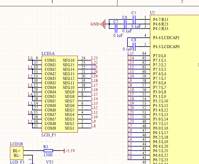
液晶接口如下图所示:
PS: 程序仿真可以正常运行。经过测试,各个IO输出正常
谢谢各位大神,求拯救。。

