

小弟最近刚刚开始学习MSP430,购买了官方的两块MSP430F5529LP开发板,现在想完成两块板子之间的通信,连接的框图如下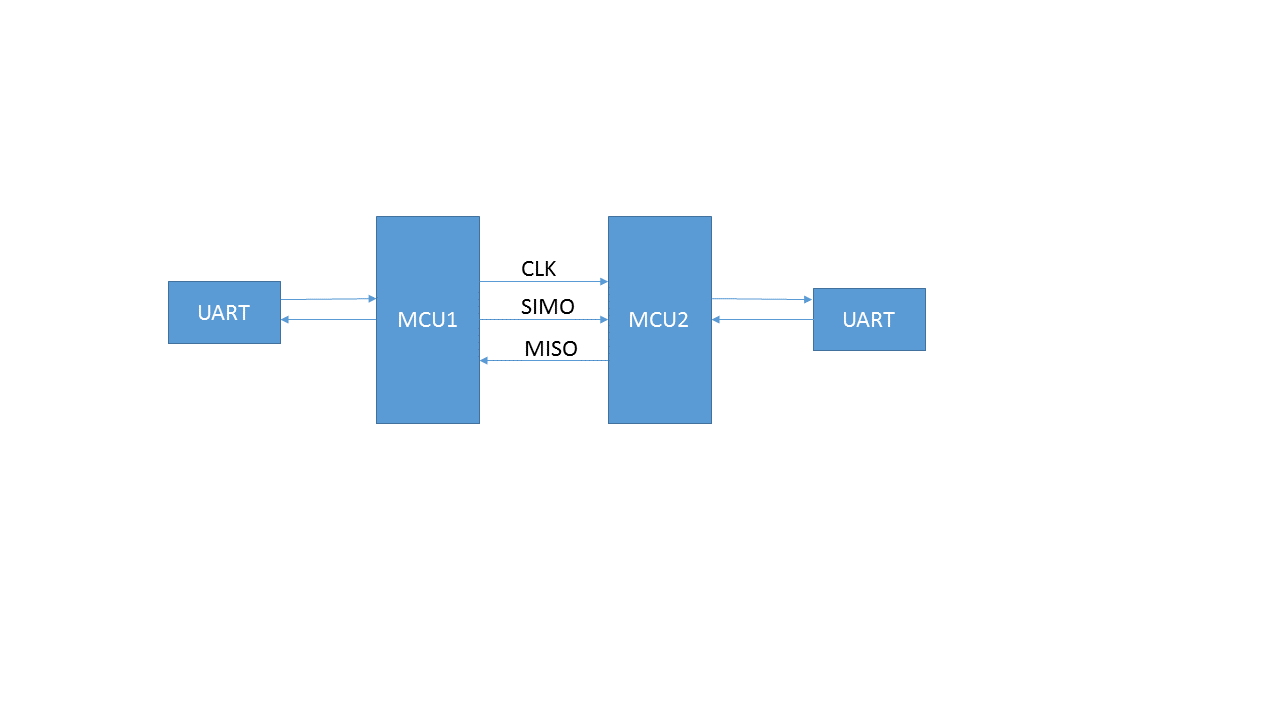
两块板子之间采用三线SPI口连接,传输输出测试时采用UART接口观察,其中两块板子的USCI_AO口配置成UART,USCI_BO口配置成SPI,均配置接受中断,现在测试过程中发现以下两个问题希望可以得到解答:
1、将测试数据从MCU1的UART输入,MCU2的UART能正常接受到数据,但是同时MCU1的UART接受到0X00;
2、将测试数据从MCU2的UART输入,MCU1未能接收到任何数据
主机MCU1代码如下:
/////////////////////////master/////////////////////
#include <msp430f5529.h>
 void clock_init(void);
 void uart_init(void);
 void spi_init(void);
 void led1_init(void);
 void led2_init(void);
 _Bool  uart_state=0;    //show the state of uart, if uart_state=0,no data
 _Bool  spi_state =0;    //show the state of spi, if spi_state = 0, no data
void main(void)
{
  WDTCTL = WDTPW + WDTHOLD;                 // Stop WDT
  clock_init();
  uart_init();
  spi_init();
  led1_init();
  led2_init();
  __bis_SR_register(GIE);       // interrupts enabled
  while(1)
  {
    if(uart_state)
    {
      while (!(UCB0IFG&UCTXIFG));             // USCI_B0 TX buffer ready?
      UCB0TXBUF = UCA0RXBUF;
      uart_state=0;
    }
    if(spi_state)
    {
      while (!(UCA0IFG&UCTXIFG));             // USCI_A0 TX buffer ready?
      UCA0TXBUF = UCB0RXBUF;                  // TX -> RXed character
      spi_state=0;
    }
  }
}
/*********************************************************************************
//初始化时钟,选用XT2作为SMCLK和MCLK的频率
***********************************************************************************/
void clock_init(void)
{
  P5SEL |= BIT2|BIT3; //将IO配置为XT2功能
  UCSCTL6 &= ~XT2OFF; //使能XT2

  UCSCTL4 = UCSCTL4&(~(SELA_7))|SELA_1; //先将ACLK配置为VLOCLK
  UCSCTL3 |= SELREF_2;                  //将REFCLK配置为REFCLK

  while (SFRIFG1 & OFIFG){
    UCSCTL7 &= ~(XT2OFFG + XT1LFOFFG + DCOFFG);         // 清除三类时钟标志位
                              // 这里需要清除三种标志位,因为任何一种
                              // 标志位都会将OFIFG置位
    SFRIFG1 &= ~OFIFG;                                  // 清除时钟错误标志位
  }
  UCSCTL4 = UCSCTL4&(~(SELS_7|SELM_7))|SELS_5|SELM_5;     //将SMCLK和MCLK时钟源配置为XT2
}

/*********************************************************************************
//初始化串口,宣统P3.3,4作为TXD/RXD,波特率为115200
*********************************************************************************/
void uart_init(void)
{
  P3SEL = BIT3+BIT4;                        // P3.3,4 = USCI_A0 TXD/RXD
  UCA0CTL1 |= UCSWRST;                      // **Put state machine in reset**
  UCA0CTL1 |= UCSSEL_2;                     // CLK = MCLK
  UCA0BR0 = 0x22;                           //
  UCA0BR1 = 0x00;                           //
  UCA0MCTL = UCBRS_6+UCBRF_0;               // Modulation UCBRSx=3, UCBRFx=0
  UCA0CTL1 &= ~UCSWRST;                     // **Initialize USCI state machine**
  UCA0IE |= UCRXIE;  // Enable USCI_A0 RX interrupt
}

/*********************************************************************************
//初始LED1,P1.0灯作为调试工具
*********************************************************************************/
void led1_init(void)
{
  P1DIR |= BIT0;                            // P1.0 set as output
  P1OUT &= ~BIT0;                            // P1.0 set as 0
}

/*********************************************************************************
//初始LED2,P4.7灯作为调试工具
*********************************************************************************/
void led2_init(void)
{
  P4DIR |= BIT7;                            // P1.0 set as output
  P4OUT &= ~BIT7;                            // P1.0 set as 0
}

/*********************************************************************************
//初始化SPI接口
*********************************************************************************/
void spi_init(void)
{
  P3SEL |= BIT0+ BIT1+BIT2;      //P3.0,1,2option select,BIT2= clock
  UCB0CTL1 |= UCSWRST;
  UCB0CTL0 |= UCMST+UCSYNC+UCCKPL+UCMSB;
  UCB0CTL1 |= UCSSEL_2;                     // SMCLK
  UCB0BR0 = 0x22;                           // /2
  UCB0BR1 = 0x00;                              //
  //UCB0MCTL = 0;                             // No modulation
  UCB0CTL1 &= ~UCSWRST;                     // **Initialize USCI state machine**
  UCB0IE |= UCRXIE;                         // Enable USCI_B0 RX interrupt
}
/*********************************************************************************
//中断函数,处理串口接受的中断
*********************************************************************************/
#pragma vector=USCI_A0_VECTOR
__interrupt void USCI_A0_ISR(void)
{
  switch(__even_in_range(UCA0IV,4))
  {
  case 0:break;                             // Vector 0 - no interrupt
  case 2:                                   // Vector 2 - RXIFG
    //while (!(UCB0IFG&UCTXIFG));             // USCI_B0 TX buffer ready?
    //UCB0TXBUF = UCA0RXBUF;                  // TX -> RXed character
    if(! uart_state)
    {
      uart_state = 1;
    }
    else
    {
      P1OUT |= BIT0;
    }
    break;
  case 4:break;                             // Vector 4 - TXIFG
  default: break;
  }
}
/*********************************************************************************
//中断函数,处理SPI接受的中断
*********************************************************************************/
#pragma vector=USCI_B0_VECTOR
__interrupt void USCI_B0_ISR(void)
{
  switch(__even_in_range(UCB0IV,4))
  {
  case 0:break;                             // Vector 0 - no interrupt
  case 2:                                   // Vector 2 - RXIFG
    if(! spi_state)
    {
      spi_state = 1;
    }
    else
    {
      P4OUT |= BIT7;
    }
    break;
  case 4:break;                             // Vector 4 - TXIFG
  default: break;
  }
}
从机MCU2的代码如下:
/*******************************slave*******************************************/
#include <msp430f5529.h>
 void clock_init(void);
 void uart_init(void);
 void spi_init(void);
 void led1_init(void);
 void led2_init(void);
 _Bool  uart_state=0;    //show the state of uart, if uart_state=0,no data
 _Bool  spi_state =0;    //show the state of spi, if spi_state = 0, no data
void main(void)
{
  WDTCTL = WDTPW + WDTHOLD;                 // Stop WDT
  clock_init();
  uart_init();
  spi_init();
  led1_init();
  led2_init();
  __bis_SR_register(GIE);       //interrupts enabled
  while(1)
  {
    if(uart_state)
    {
      while (!(UCB0IFG&UCTXIFG));             // USCI_B0 TX buffer ready?
      UCB0TXBUF = UCA0RXBUF;
      uart_state=0;
    }
    if(spi_state)
    {
      while (!(UCA0IFG&UCTXIFG));             // USCI_A0 TX buffer ready?
      UCA0TXBUF = UCB0RXBUF;                  // TX -> RXed character
      spi_state =0;
    }
  }
}
/*********************************************************************************
//初始化时钟,选用XT2作为SMCLK和MCLK的频率
***********************************************************************************/
void clock_init(void)
{
  P5SEL |= BIT2|BIT3; //将IO配置为XT2功能
  UCSCTL6 &= ~XT2OFF; //使能XT2

  UCSCTL4 = UCSCTL4&(~(SELA_7))|SELA_1; //先将ACLK配置为VLOCLK
  UCSCTL3 |= SELREF_2;                  //将REFCLK配置为REFCLK

  while (SFRIFG1 & OFIFG){
    UCSCTL7 &= ~(XT2OFFG + XT1LFOFFG + DCOFFG);         // 清除三类时钟标志位
                              // 这里需要清除三种标志位,因为任何一种
                              // 标志位都会将OFIFG置位
    SFRIFG1 &= ~OFIFG;                                  // 清除时钟错误标志位
  }
  UCSCTL4 = UCSCTL4&(~(SELS_7|SELM_7))|SELS_5|SELM_5;     //将SMCLK和MCLK时钟源配置为XT2
}

/*********************************************************************************
//初始化串口,宣统P3.3,4作为TXD/RXD,波特率为115200
*********************************************************************************/
void uart_init(void)
{
  P3SEL = BIT3+BIT4;                        // P3.3,4 = USCI_A0 TXD/RXD
  UCA0CTL1 |= UCSWRST;                      // **Put state machine in reset**
  UCA0CTL1 |= UCSSEL_2;                     // CLK = MCLK
  UCA0BR0 = 0x22;                           //
  UCA0BR1 = 0x00;                           //
  UCA0MCTL = UCBRS_6+UCBRF_0;               // Modulation UCBRSx=3, UCBRFx=0
  UCA0CTL1 &= ~UCSWRST;                     // **Initialize USCI state machine**
  UCA0IE |= UCRXIE;  // Enable USCI_A0 RX interrupt
}

/*********************************************************************************
//初始LED1,P1.0灯作为调试工具
*********************************************************************************/
void led1_init(void)
{
  P1DIR |= BIT0;                            // P1.0 set as output
  P1OUT &= ~BIT0;                            // P1.0 set as 0
}

/*********************************************************************************
//初始LED2,P4.7灯作为调试工具
*********************************************************************************/
void led2_init(void)
{
  P4DIR |= BIT7;                            // P1.0 set as output
  P4OUT &= ~BIT7;                            // P1.0 set as 0
}

/*********************************************************************************
//初始化SPI接口
*********************************************************************************/
void spi_init(void)
{
  P3SEL |= BIT0+ BIT1+BIT2;      //P3.0,1,2option select,BIT2= clock
  UCB0CTL1 |= UCSWRST;
  UCB0CTL0 |= UCSYNC+UCCKPL+UCMSB;                             //
  //UCB0MCTL = 0;                             // No modulation
  UCB0CTL1 &= ~UCSWRST;                     // **Initialize USCI state machine**
  UCB0IE |= UCRXIE;                         // Enable USCI_B0 RX interrupt
}
/*********************************************************************************
//中断函数,处理串口接受的中断
*********************************************************************************/
#pragma vector=USCI_A0_VECTOR
__interrupt void USCI_A0_ISR(void)
{
  switch(__even_in_range(UCA0IV,4))
  {
  case 0:break;                             // Vector 0 - no interrupt
  case 2:                                   // Vector 2 - RXIFG
    //while (!(UCB0IFG&UCTXIFG));             // USCI_B0 TX buffer ready?
    //UCB0TXBUF = UCA0RXBUF;                  // TX -> RXed character
    if(! uart_state)
    {
      uart_state = 1;
    }
    else
    {
      P1OUT |= BIT0;
    }
    break;
  case 4:break;                             // Vector 4 - TXIFG
  default: break;
  }
}
/*********************************************************************************
//中断函数,处理SPI接受的中断
*********************************************************************************/
#pragma vector=USCI_B0_VECTOR
__interrupt void USCI_B0_ISR(void)
{
  switch(__even_in_range(UCB0IV,4))
  {
  case 0:break;                             // Vector 0 - no interrupt
  case 2:                                   // Vector 2 - RXIFG
    //while (!(UCA0IFG&UCTXIFG));             // USCI_A0 TX buffer ready?
    //UCA0TXBUF = UCB0RXBUF;                  // TX -> RXed character
    if(! spi_state)
    {
      spi_state = 1;
    }
    else
    {
      P4OUT |= BIT7;
    }
    break;
  case 4:break;                             // Vector 4 - TXIFG
  default: break;
  }
}

