根据官网的SDK文件包,来创建自己的工程文件,使用KEIL开发环境通过GPIO驱动LED灯,来测试工程文件。
一、硬件
板卡硬件LED部分电路图,板卡上有一个LED1和一个RGB LED2。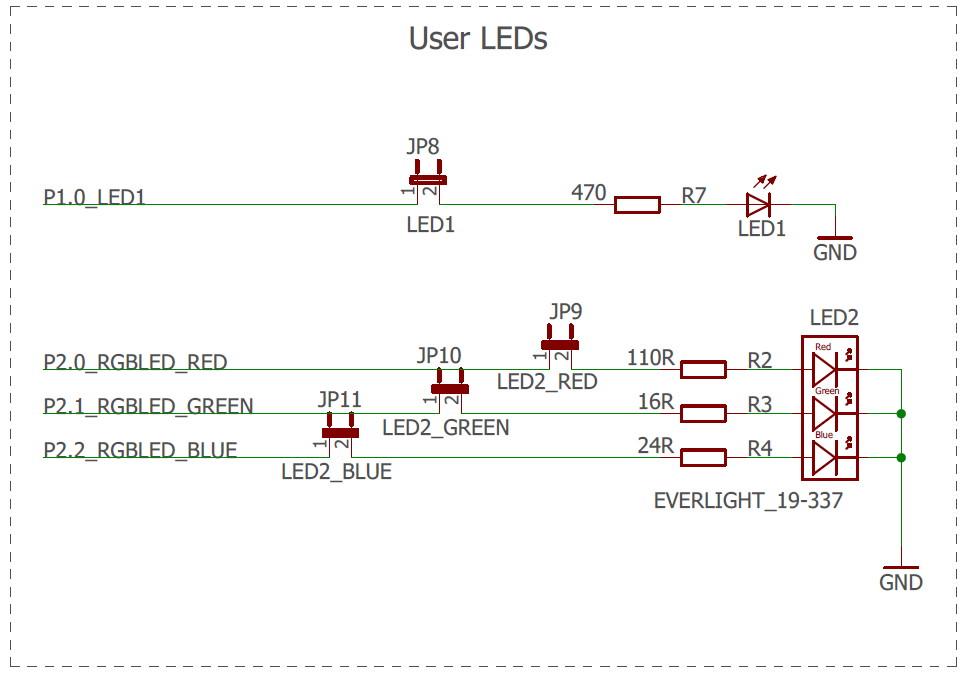
二、创建自己的项目文件
下载开发板的SDK文件: SDK

SDK里面有完整工程文件,我从中选取相关的文件创建自己的项目文件。
三、程序
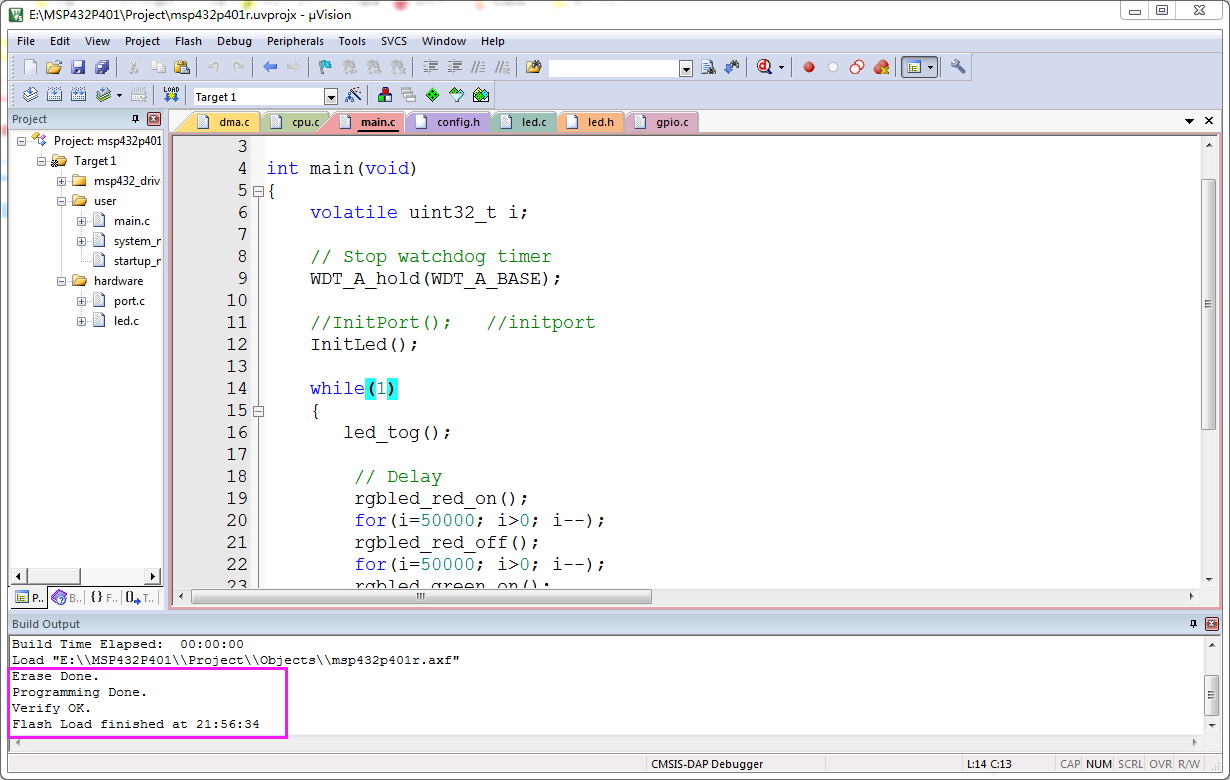
3.1、main.c
#include "config.h"

int main(void)
{
    volatile uint32_t i;

    // Stop watchdog timer
    WDT_A_hold(WDT_A_BASE);

		//InitPort();		//initport
		InitLed();

    while(1)
    {
       led_tog();

        // Delay
				rgbled_red_on();
        for(i=50000; i>0; i--);
				rgbled_red_off();
        for(i=50000; i>0; i--);
				rgbled_green_on();
        for(i=50000; i>0; i--);
				rgbled_green_off();
        for(i=50000; i>0; i--);
				rgbled_blue_on();
        for(i=50000; i>0; i--);
				rgbled_blue_off();
        for(i=50000; i>0; i--);
    }
}
3.2、led.c
#include "config.h"


//initled
void InitLed(void)
{
	 // Set P1.0 to output direction
	GPIO_setAsOutputPin( GPIO_PORT_P1,GPIO_PIN0);

	GPIO_setAsOutputPin( GPIO_PORT_P2,GPIO_PIN0);
	GPIO_setAsOutputPin( GPIO_PORT_P2,GPIO_PIN1);
	GPIO_setAsOutputPin( GPIO_PORT_P2,GPIO_PIN2);

	rgbled_red_off();
	rgbled_green_off();
	rgbled_blue_off();
}
3.3、led.h
#ifndef LED_H_
#define LED_H_

void InitLed(void);

#define led_tog() GPIO_toggleOutputOnPin( GPIO_PORT_P1,GPIO_PIN0 ); // Toggle P1.0 output
#define rgbled_red_on() 		GPIO_setOutputHighOnPin( GPIO_PORT_P2,GPIO_PIN0 );
#define rgbled_red_off()		GPIO_setOutputLowOnPin( GPIO_PORT_P2,GPIO_PIN0 );

#define rgbled_green_on() 	GPIO_setOutputHighOnPin( GPIO_PORT_P2,GPIO_PIN1 );
#define rgbled_green_off()	GPIO_setOutputLowOnPin( GPIO_PORT_P2,GPIO_PIN1 );

#define rgbled_blue_on() 		GPIO_setOutputHighOnPin( GPIO_PORT_P2,GPIO_PIN2 );
#define rgbled_blue_off()		GPIO_setOutputLowOnPin( GPIO_PORT_P2,GPIO_PIN2 );
#endif
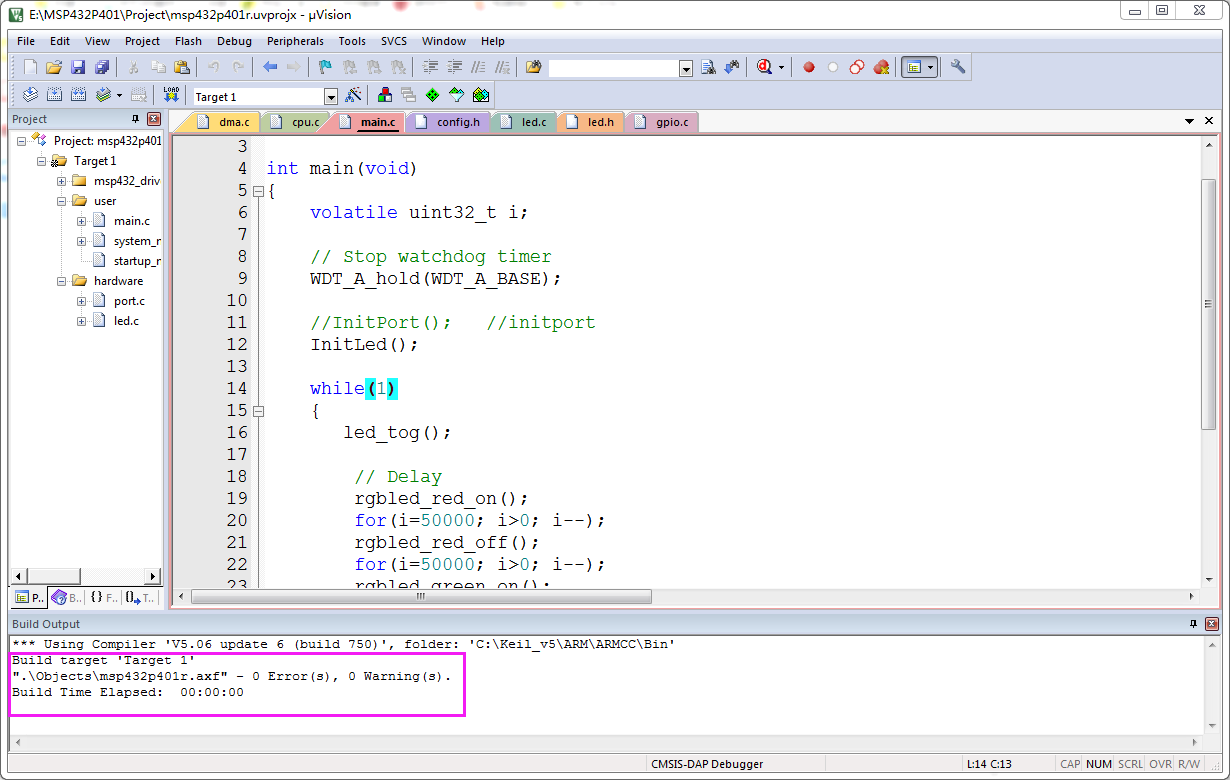
四、编译
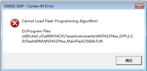
五、下载
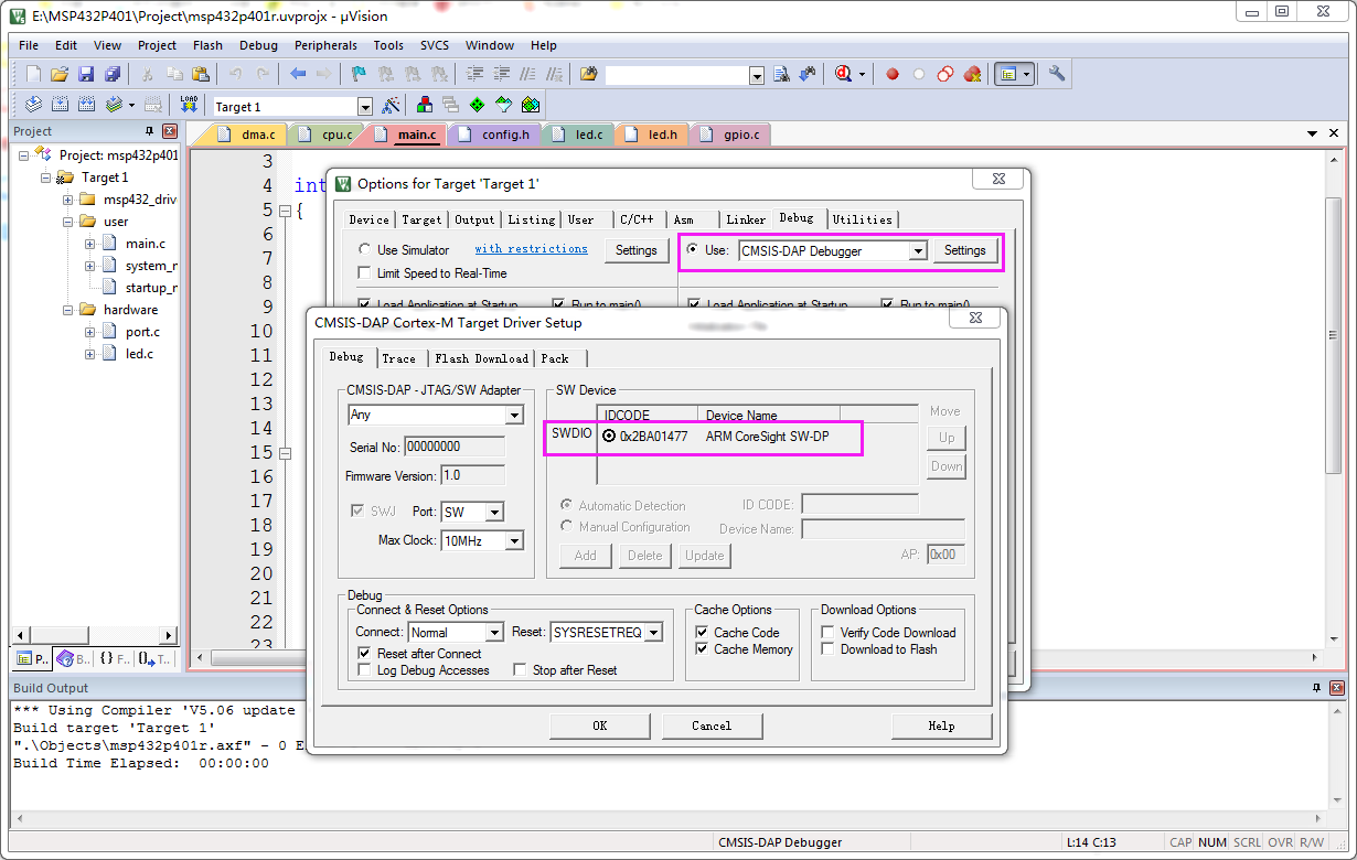
5.1、设置仿真器
5.2、下载程序
六、执行结果
LED1和RGB LED2交替闪烁。