This thread has been locked.

If you have a related question, please click the "Ask a related question" button in the top right corner. The newly created question will be automatically linked to this question.

关于SD24模块的使用

Other Parts Discussed in Thread: MSP430F6779

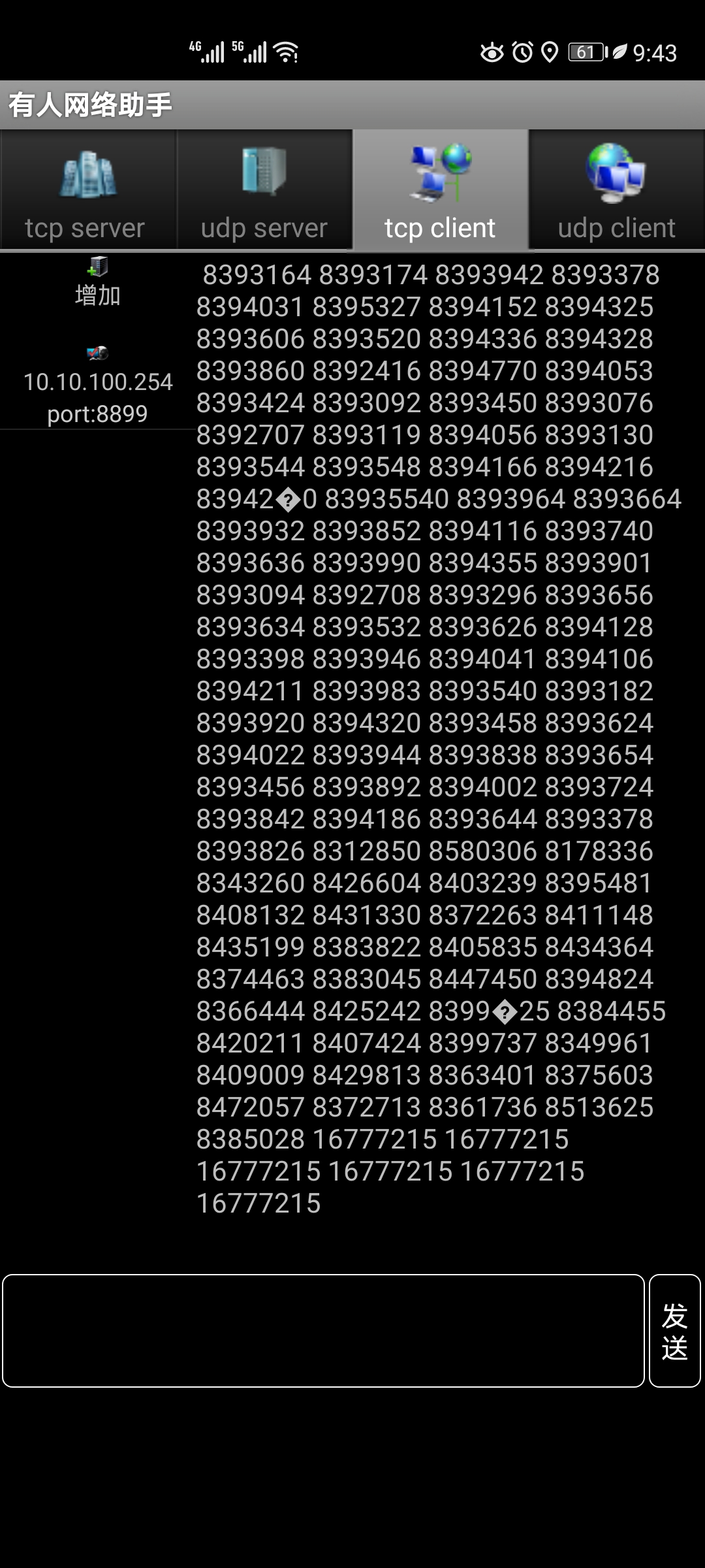
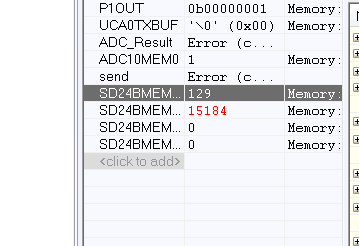
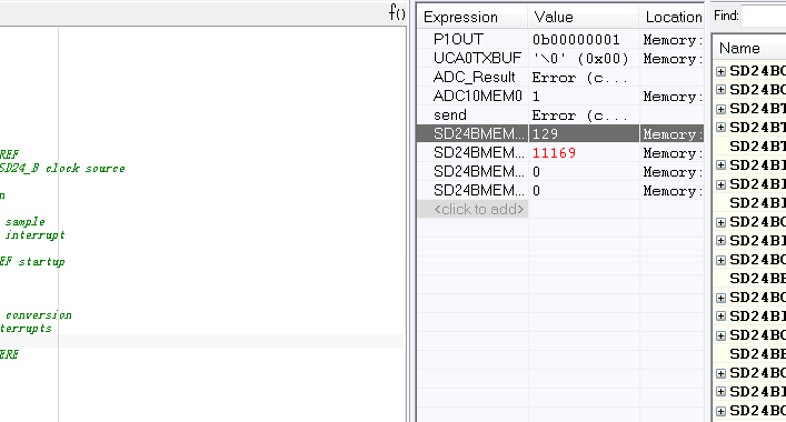
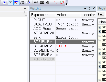
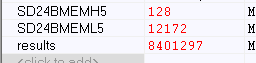
目前使用的是MSP430F6779模块,测试其24位AD模块,使用时发现很大问题,输入为电压为0时,结果寄存器仍然有值,100nf电容已接,代码是在官方例程上修改的,代码如下。
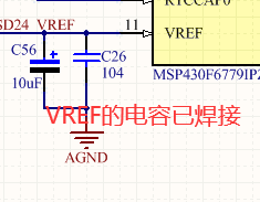
#include <msp430.h>
#include <string.h>
#include "stdlib.h"
#include <stdio.h>
/* Unsigned integer to store SD24_B conversion result */
 long results;
 char send[12];

void initUART()
{    UCSCTL6 &= ~(XT1OFF);                    // XT1 On
    UCSCTL6 |= XCAP_1;                       // Internal load cap
    // Loop until XT1 fault flag is cleared
    do
    {
        UCSCTL7 &= ~(XT2OFFG | XT1LFOFFG | DCOFFG);
        // Clear XT2,XT1,DCO fault flags
        SFRIFG1 &= ~OFIFG;                   // Clear fault flags
    } while (SFRIFG1 & OFIFG); 
    UCSCTL6 &= ~(XT1DRIVE_3);
      
    // Configure USCI_A0 for UART mode
    UCA0CTLW0 = UCSWRST;                    // Put eUSCI in reset

      UCA0CTLW0 |= UCSSEL__SMCLK;              // CLK = SMCLK     bode率  115200
      UCA0BRW = 8;
      UCA0MCTLW = 0xD600;                     // UCBRSx = 0x92, UCOS16 = 0
      
      
    UCA0CTLW0 &= ~UCSWRST;                    // Initialize eUSCI
 
}

void send_buf( long ptr)    //AD数据无线发送
{   
          int i =0;
          sprintf(send,"%ld",ptr);    //将AD数值转化为字符串进行无线发送
      
          while(send[i] != '\0') 
          { 
          UCA0TXBUF = send[i];
          while(!(UCA0IFG&UCTXIFG)); 
          i++;
          __delay_cycles(5000);
           }    
}

void main(void)
{
   
    
    WDTCTL = WDTPW | WDTHOLD;                       // Stop WDT
    
    initUART();
    P3SEL0 |= BIT0 + BIT1;                    // Set P3.0, P3.1 to non-IO
    P3DIR |=  BIT0 + BIT1;                     // Enable UCA0RXD, UCA0TXD
    
    P5DIR |=  BIT0;                       //指示灯
    P1DIR |=  BIT0;                       //P1 输出测试高电压
    P1OUT |= BIT0;
    
    
    SD24BCTL0 = SD24REFS | SD24SSEL_1;              // Select internal REF
                                                    // Select SMCLK as SD24_B clock source

    SD24BCCTL6 |= SD24SNGL;                         // Single conversion

    SD24BINCTL6 |= SD24INTDLY0;                     // Interrupt on 3rd sample
    SD24BIE |= SD24IE6;                             // Enable channel 2 interrupt

    __delay_cycles(0x3600);                         // Delay for 1.5V REF startup
__bis_SR_register( GIE);         // Enter LPM0 w/ interrupts
    while (1)
    {   P5OUT ^= BIT0;        //运行闪烁指示灯
        SD24BCCTL6 |= SD24SC;                       // Set bit to start conversion
     
       send_buf(results);// ad值发送
        __delay_cycles(500000);   
        UCA0TXBUF = '\r';//换行符
    }
}


#pragma vector=SD24B_VECTOR
__interrupt void SD24BISR(void)

{
    switch (SD24BIV)
    {
        case SD24BIV_SD24OVIFG:                     // SD24MEM Overflow
            break;
        case SD24BIV_SD24TRGIFG:                    // SD24 Trigger IFG
            break;
        case SD24BIV_SD24IFG0:                      // SD24MEM0 IFG
            break;
        case SD24BIV_SD24IFG1:                      // SD24MEM1 IFG
            break;
        case SD24BIV_SD24IFG6:                      // SD24MEM2 IFG
            results = SD24BMEMH6;                   // Save CH2 results (clears IFG)
            results = (results << 16) | SD24BMEML6; // Concatenate lower and upper words
            
            break;
        default:break;
    }

  
}

  • 这个是接收的results如下

  • 请您先使用TI例程简单测试一下(先不要测试无线等功能,单纯测试SD24),看是否能成功

  • 您好,我刚刚原封不动的按照官方例程进行了测试,我用的是通道5,为了排除干扰我将正负端都接DGND,但是任然有很大的数值,且SD24BMEML5这个寄存器里的值一直在变,我截取了三次数值如下。另外,我昨天测试了ADC10模块,还算正常,没有接入时,转换结果显示5左右误差不大,这个SD24不知道为什么差距这么大。

  • 请问您使用的具体是哪个例程?观测的话,请观察变量 result

    如下面的例程 观测的是 SD24BMEMH2 是高16位upper 16 bits

    dev.ti.com/.../node

    Test by applying a voltage to channel 2 (SD2P0, SD2N0) and setting a breakpoint at the line indicated below. Run program until it reaches the breakpoint, then use the debugger's watch window to view the conversion results. Results (upper 16 bits only) for channel 2 are stored in variable "results".
  • 测试代码如下,按照例程的意思是将高低寄存器里面的值进行计算求和后存入results变量里面。


    #include <msp430.h> /* Unsigned integer to store SD24_B conversion result */ unsigned long results; void main(void) { WDTCTL = WDTPW | WDTHOLD; // Stop WDT SD24BCTL0 = SD24REFS | SD24SSEL_1; // Select internal REF // Select SMCLK as SD24_B clock source SD24BCCTL5 |= SD24SNGL; // Single conversion SD24BINCTL5 |= SD24INTDLY0; // Interrupt on 3rd sample SD24BIE |= SD24IE5; // Enable channel 2 interrupt __delay_cycles(0x3600); // Delay for 1.5V REF startup while (1) { SD24BCCTL5 |= SD24SC; // Set bit to start conversion __bis_SR_register(LPM0_bits | GIE); // Enter LPM0 w/ interrupts __no_operation(); __no_operation(); // SET BREAKPOINT HERE } } #if defined(__TI_COMPILER_VERSION__) || defined(__IAR_SYSTEMS_ICC__) #pragma vector=SD24B_VECTOR __interrupt void SD24BISR(void) #elif defined(__GNUC__) void __attribute__ ((interrupt(SD24B_VECTOR))) SD24BISR (void) #else #error Compiler not supported! #endif { switch (SD24BIV) { case SD24BIV_SD24OVIFG: // SD24MEM Overflow break; case SD24BIV_SD24TRGIFG: // SD24 Trigger IFG break; case SD24BIV_SD24IFG0: // SD24MEM0 IFG break; case SD24BIV_SD24IFG1: // SD24MEM1 IFG break; case SD24BIV_SD24IFG5: // SD24MEM2 IFG results = SD24BMEMH5; // Save CH2 results (clears IFG) results = (results << 16) | SD24BMEML5; // Concatenate lower and upper words break; default:break; } __bic_SR_register_on_exit(LPM0_bits); // Exit LPM0 }

  • 所以您现在的result以及寄存器的全部名称和数值可以给出截图吗?

    另外请给出您的详细原理图(SD24部分),谢谢
  • 刚刚又进行了很多测试,将SD5P0,SD5N0都接地,然后我直接将其用跳线帽短接发现显示结果和上图大同小异(图为跳线帽短接后测试结果)。原理图部分很简单,如下。

  • 很抱歉,我找了一下,手边没有该型号的板子,所以在英文论坛上发了链接,请您跟踪/补充一下,谢谢

    e2e.ti.com/.../965958
  • 恩恩我看到了,多谢您的帮助!我静候一下他们的回答!

  • 另外我看到一个老帖子也反映了类似的问题e2echina.ti.com/.../96582

  • 谢谢您的反馈!
  • 老师您好!我今天又进行了测试,用反向电压信号接入通道,发现反向输入1V左右电压时results的值近似为0 ,不知对这种情况您是否原来见过。?

  • 请您在下面帖子内补充一下您的问题,会有对应的工程师回复,谢谢

    e2e.ti.com/.../965958
x 出现错误。请重试或与管理员联系。