This thread has been locked.
If you have a related question, please click the "Ask a related question" button in the top right corner. The newly created question will be automatically linked to this question.
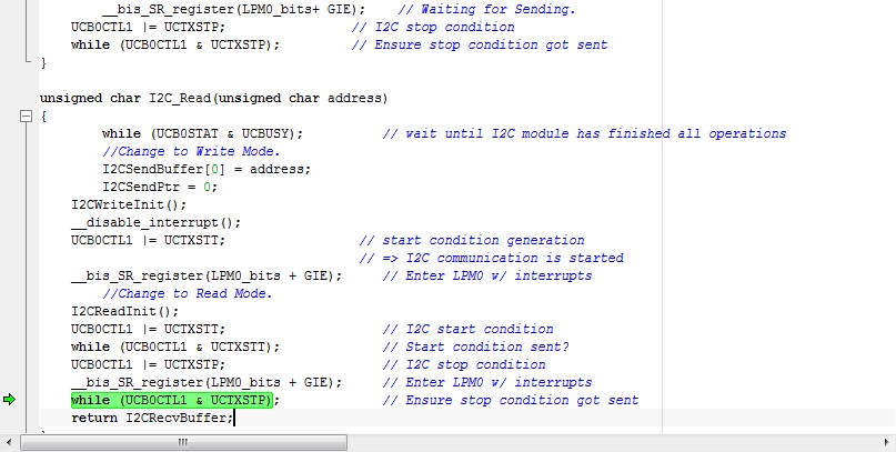
在I2C通信的过程中,读取代码,读取协议以及波形记录如上,为什么波形上读不出数据?
从波形上看,问题主要出现在第二个UCB0CTL1 |=UCTXTT;这句上,如果要改,应该怎么改?
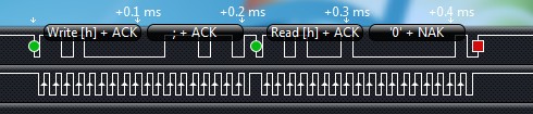
你的波形有2个问题
1. 这个波形中,第8个CLK是用来指示读、写命令的,0表示写,1表示读。在本波形中是写操作,而不是读操作。说明你在I2CReadInit函数中,没有把UCBXCTL1的UCTR置0.
2. 即使是写操作,在本波形中第9个CLK时,从设备也没有给出ACK信号。说明你写的设备地址有问题。你可以把你从设备的地址描述部分贴出来看下。
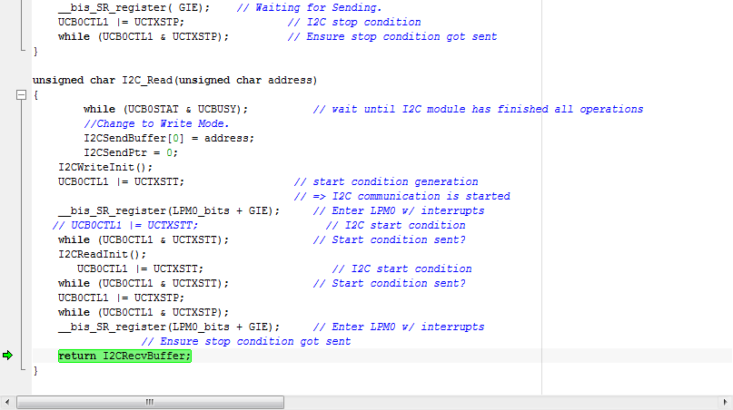
我之前写程序的时候好像把从设备的某寄存器改了,导致发不回ack,换了块,然后通信似乎是回复了,但是程序卡在了一个地方,求教
UCB0I2CSA = 0x68;
// USCI_B0 Data ISR// Notice : UCSIAB0RX_ISR should be handle with UCSIAB0TX_ISR#pragma vector = USCIAB0TX_VECTOR__interrupt void USCIAB0TX_ISR(void){ if (IFG2 & UCB0TXIFG) // TX { UCB0TXBUF = I2CSendBuffer[I2CSendPtr]; // Load TX buffer I2CSendPtr--; // Decrement TX byte counter if (I2CSendPtr < 0) { while (!(IFG2 & UCB0TXIFG)); // wait for tx complete IE2 &= ~UCB0TXIE; // disable interrupts. IFG2 &= ~UCB0TXIFG; // Clear USCI_B0 TX int flag
} } if (IFG2 & UCB0RXIFG) // RX { I2CRecvBuffer = UCB0RXBUF; // store received data in buffer
} __bic_SR_register_on_exit(LPM0_bits);}
这个是中断
从你给出的波形看,salve没有ACK。