

void TimerA1Init(void)
{ TA1CTL |= TASSEL_1; //设定时钟为ACLK, TA1CTL |= ID_0; //不分频
TA1CCR0 = VOLC-1; //波形周期,根据计时器时钟周期计算
TA1CCR2 = 0; //default
TA1CCTL2 |= OUTMOD_3; //PWM输出模式3,P2.4
TA1CTL |= MC_1; //增计数模式,MC_0可以停止
}
void PortTwoInit(void)
{ P2DIR |= 0xf3;
P2OUT = 0x14; //P2.2 for KeyA input, enable pull up resistor
P2REN |= 0x04; //p2.4 p2.2 pulled up
P2SEL &= ~BIT4;
}
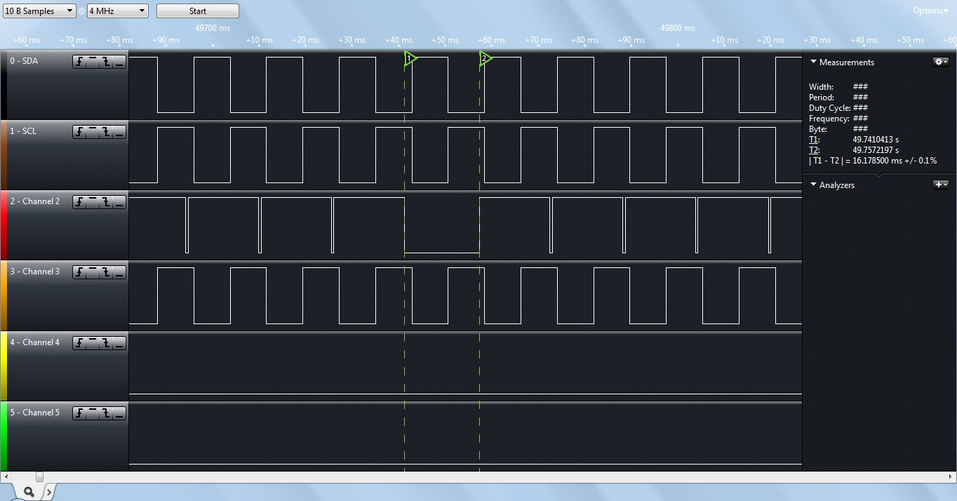
通过软件控制修改TA1CCR2的值,理论上其值在3~45直接循环变换,但软件在调试的过程中,发现异常波形,如附件,chanel2中2条虚线直接的波形正常应该如前或后的波形,现在为全部低电平,请问是什么原因呢?
