Part Number: TIDM-02013
Other Parts Discussed in Thread: PMP22650
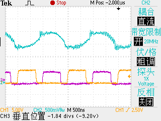
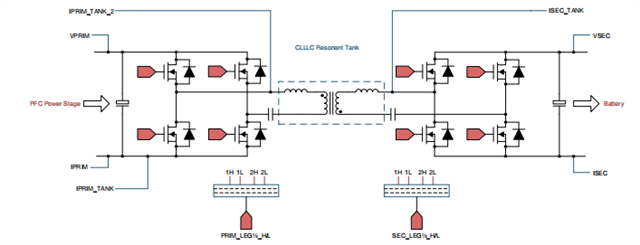
The blue waveform represents the secondary - side current, while the others are the two - channel secondary - side driving signals. As shown in the figure, the synchronous rectification (SR) operation should be functioning properly. However, during the experiment, when the secondary - side driving was enabled, the input voltage rose sharply. Under this condition, the input voltage was set at 10 V with a connected load of 20 Ω, but the input current had already reached 3 A. Subsequently, when I replaced the load resistor with a 100 - Ω one, the input voltage and current remained unchanged. Therefore, it is likely that a short - circuit fault occurred in a certain part of the circuit. When the secondary - side driving was disabled and the secondary side operated temporarily as a diode bridge, both the input and output voltages and currents returned to normal levels.
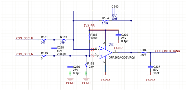
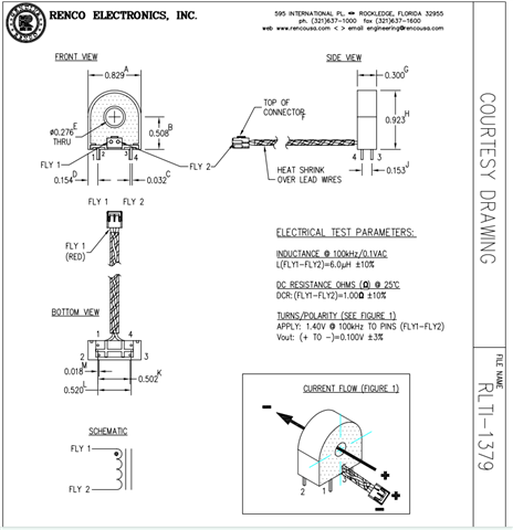
In summary, the current fault is probably caused by a short circuit in a certain circuit triggered by the enabling of the secondary - side driving. (It should be specially noted that since a Rogowski coil of the same model could not be found, a Hall sensor was adopted as the current detection scheme instead, and the blue secondary - side current waveform shown is the signal processed by an operational amplifier.) At present, I consider the possible causes of this problem as follows: 1. The current detection scheme; 2. Insufficient driving delay between the primary and secondary sides; 3. Improper synchronous rectification thresholds (set at 2100 and 2000) and insufficient blanking time.
Your reply would be highly appreciated, as this issue is of great importance to me. Thank you.