Part Number: TIDM-02013
Dear Experts,
During the Lab 1 experiment, the gate drive performed normally. Afterwards, the Lab 3 current‑loop test was carried out. When only the PH1 branch was enabled with a 200 Ω load connected, the output voltage rose gradually as the current‑loop reference was increased step‑by‑step. Finally, with a current reference of 0.17 and 220 V AC input, the output voltage reached 400 V, and the power factor was higher than 0.99.
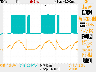
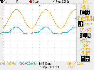
However, under identical test conditions when only the PH2 branch was enabled, gate drive signals were missing during the negative half‑cycle. Increasing the current‑loop reference failed to restore the missing drive pulses. In Figure 1, the blue trace shows the gate‑drive waveform of PH2. In Figure 2, the yellow trace denotes the input voltage and the blue trace denotes the input current. Due to this fault in the PH2 branch, the interleaved totem‑pole PFC cannot work properly.
What could be the root cause? Is it an issue with the Hall‑effect current sensor, or a firmware/code‑related problem?
This issue has troubled me for a long time. I look forward to your prompt reply. Thank you very much