
This thread has been locked.

If you have a related question, please click the "Ask a related question" button in the top right corner. The newly created question will be automatically linked to this question.

TIDM-02013: 电流环波形半周期丢失

Part Number: TIDM-02013

Dear Experts,
During the Lab 1 experiment, the gate drive performed normally. Afterwards, the Lab 3 current‑loop test was carried out. When only the PH1 branch was enabled with a 200 Ω load connected, the output voltage rose gradually as the current‑loop reference was increased step‑by‑step. Finally, with a current reference of 0.17 and 220 V AC input, the output voltage reached 400 V, and the power factor was higher than 0.99.
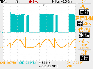
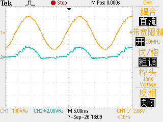
However, under identical test conditions when only the PH2 branch was enabled, gate drive signals were missing during the negative half‑cycle. Increasing the current‑loop reference failed to restore the missing drive pulses. In Figure 1, the blue trace shows the gate‑drive waveform of PH2. In Figure 2, the yellow trace denotes the input voltage and the blue trace denotes the input current. Due to this fault in the PH2 branch, the interleaved totem‑pole PFC cannot work properly.
What could be the root cause? Is it an issue with the Hall‑effect current sensor, or a firmware/code‑related problem?
This issue has troubled me for a long time. I look forward to your prompt reply. Thank you very much
F0044TEK.BMPF0043TEK.BMP

  • 已经收到了您的案例,调查需要些时间,感谢您的耐心等待。

  • 您好

    方便分享您的实际电路图吗?以及您驱动的控制信号和反馈信号。

  • Dear Expert,
    Our hardware circuit is based on TI reference design TIDM-02013. No modifications have been made to the hardware feedback and control circuits. The software current loop is implemented following the attached diagram. The hardware and software configurations of the PH1 and PH2 power paths are identical except for acceptable minor deviations. PH1 operates normally, while the PH2 path loses gate drive signals for half an AC cycle during operation.     Looking forward to your reply.
  • Dear Expert,
    Our hardware circuit is based on TI reference design TIDM-02013. No modifications have been made to the hardware feedback and control circuits. The software current loop is implemented following the attached diagram. The hardware and software configurations of the PH1 and PH2 power paths are identical except for acceptable minor deviations. PH1 operates normally, while the PH2 path loses gate drive signals for half an AC cycle during operation.
    Looking forward to your reply.
  • 您好

    我想看一下驱动控制信号变化以及反馈相关的变化。