//包含一系列头文件
#include <stdbool.h>
#include <stdint.h>
#include "inc/hw_i2c.h"
#include "inc/hw_memmap.h"
#include "inc/hw_types.h"
#include "driverlib/gpio.h"
#include "driverlib/i2c.h"
#include "driverlib/pin_map.h"
#include "driverlib/sysctl.h"
#include "driverlib/uart.h"
#include "utils/uartstdio.h"
//要发送的I2C数据包的数量
#define SysCtlDelay_ms(ms) (SysCtlDelay(ms*(SysCtlClockGet()/3000)))
#define NUM_I2C_DATA 6
//地址
#define SLAVE_ADDRESS 0x5a
#define Register_ADDRESS 0x07
/*****************************************************************************
*初始化配置使用 UART0 外设
*-UART0RX - PA0
*-UART0TX - PA1
*****************************************************************************/
void Init_Console_Uart0(void)
{
SysCtlPeripheralEnable(SYSCTL_PERIPH_GPIOA);
SysCtlPeripheralEnable(SYSCTL_PERIPH_GPIOA);
GPIOPinConfigure(GPIO_PA0_U0RX);
GPIOPinConfigure(GPIO_PA1_U0TX);
SysCtlPeripheralEnable(SYSCTL_PERIPH_UART0);
UARTClockSourceSet(UART0_BASE, UART_CLOCK_PIOSC); //内部16M时钟
GPIOPinTypeUART(GPIO_PORTA_BASE, GPIO_PIN_0 | GPIO_PIN_1);
UARTStdioConfig(0, 115200, 16000000);
}
/*****************************************************************************
*配置I2C0主机,并使用环回模式连接它们。
*初始化I2C0外设
*I2C0SCL - PB2
*I2C0SDA - PB3
*****************************************************************************/
int main(void)
{
uint32_t pui32DataTx[NUM_I2C_DATA]; // 发送数据缓冲区
uint32_t pui32DataRx[NUM_I2C_DATA]; //接受数据缓冲区
uint32_t ui32Index; //要发送数据到缓冲区的位置
//配置外部时钟为20M
SysCtlClockSet(SYSCTL_SYSDIV_1|SYSCTL_USE_OSC|SYSCTL_OSC_MAIN|SYSCTL_XTAL_16MHZ);
SysCtlPeripheralEnable(SYSCTL_PERIPH_I2C0); //使能I2C0外设
SysCtlPeripheralEnable(SYSCTL_PERIPH_GPIOB); //使能PB端口
//配置引脚的复用功能 PB2 PB3
GPIOPadConfigSet(GPIO_PORTB_BASE,GPIO_PIN_2,GPIO_STRENGTH_8MA,GPIO_PIN_TYPE_STD_WPU);
GPIOPadConfigSet(GPIO_PORTB_BASE,GPIO_PIN_3,GPIO_STRENGTH_8MA,GPIO_PIN_TYPE_OD);
GPIOPinConfigure(GPIO_PB2_I2C0SCL);
GPIOPinConfigure(GPIO_PB3_I2C0SDA);
//配置I2C引脚
GPIOPinTypeI2CSCL(GPIO_PORTB_BASE, GPIO_PIN_2);
GPIOPinTypeI2C(GPIO_PORTB_BASE, GPIO_PIN_3);
//I2CLoopbackEnable(I2C0_BASE);
HWREG(I2C0_BASE + I2C_O_MCR) |= 0x01; //调用寄存器的环回模式 (改用寄存器实现)
//初始化并使能主机模式,使用系统时钟为 I2C0 模块提供时钟频率,
//主机模块传输速//率为 100Kbps
I2CMasterInitExpClk(I2C0_BASE, SysCtlClockGet(), false);
//设置主机放在总线上的地址,写入从机 write
I2CMasterSlaveAddrSet(I2C0_BASE, SLAVE_ADDRESS, false);
//调用uart初始化函数串口显示
Init_Console_Uart0();
I2CMasterDataPut(I2C0_BASE, Register_ADDRESS);
//从机回显发送数据到主机
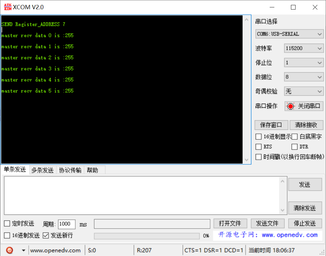
UARTprintf("\nSEND Register_ADDRESS %d\n", Register_ADDRESS);
I2CMasterControl(I2C0_BASE, I2C_MASTER_CMD_SINGLE_SEND);
while(I2CMasterBusy(I2C0_BASE));
{
uint32_t pui32DataTx[NUM_I2C_DATA]; // 发送数据缓冲区
uint32_t pui32DataRx[NUM_I2C_DATA]; //接受数据缓冲区
uint32_t ui32Index; //要发送数据到缓冲区的位置
//配置外部时钟为20M
SysCtlClockSet(SYSCTL_SYSDIV_1|SYSCTL_USE_OSC|SYSCTL_OSC_MAIN|SYSCTL_XTAL_16MHZ);
SysCtlPeripheralEnable(SYSCTL_PERIPH_I2C0); //使能I2C0外设
SysCtlPeripheralEnable(SYSCTL_PERIPH_GPIOB); //使能PB端口
//配置引脚的复用功能 PB2 PB3
GPIOPadConfigSet(GPIO_PORTB_BASE,GPIO_PIN_2,GPIO_STRENGTH_8MA,GPIO_PIN_TYPE_STD_WPU);
GPIOPadConfigSet(GPIO_PORTB_BASE,GPIO_PIN_3,GPIO_STRENGTH_8MA,GPIO_PIN_TYPE_OD);
GPIOPinConfigure(GPIO_PB2_I2C0SCL);
GPIOPinConfigure(GPIO_PB3_I2C0SDA);
//配置I2C引脚
GPIOPinTypeI2CSCL(GPIO_PORTB_BASE, GPIO_PIN_2);
GPIOPinTypeI2C(GPIO_PORTB_BASE, GPIO_PIN_3);
//I2CLoopbackEnable(I2C0_BASE);
HWREG(I2C0_BASE + I2C_O_MCR) |= 0x01; //调用寄存器的环回模式 (改用寄存器实现)
//初始化并使能主机模式,使用系统时钟为 I2C0 模块提供时钟频率,
//主机模块传输速//率为 100Kbps
I2CMasterInitExpClk(I2C0_BASE, SysCtlClockGet(), false);
//设置主机放在总线上的地址,写入从机 write
I2CMasterSlaveAddrSet(I2C0_BASE, SLAVE_ADDRESS, false);
//调用uart初始化函数串口显示
Init_Console_Uart0();
I2CMasterDataPut(I2C0_BASE, Register_ADDRESS);
//从机回显发送数据到主机
UARTprintf("\nSEND Register_ADDRESS %d\n", Register_ADDRESS);
I2CMasterControl(I2C0_BASE, I2C_MASTER_CMD_SINGLE_SEND);
while(I2CMasterBusy(I2C0_BASE));
I2CMasterSlaveAddrSet(I2C0_BASE, SLAVE_ADDRESS, true);
// 初始化I2C主机模块状态为单端接收
I2CMasterControl(I2C0_BASE, I2C_MASTER_CMD_BURST_RECEIVE_START);
// 初始化I2C主机模块状态为单端接收
for (ui32Index = 0; ui32Index < NUM_I2C_DATA; ui32Index++){
I2CMasterControl(I2C0_BASE, I2C_MASTER_CMD_BURST_RECEIVE_CONT);
// 从主机数据寄存器读取数据
SysCtlDelay_ms(20);
pui32DataRx[ui32Index] = I2CMasterDataGet(I2C0_BASE);
UARTprintf("\nmaster recv data %d is :%d\n",ui32Index , pui32DataRx[ui32Index]);
}
return 0;
}
// 初始化I2C主机模块状态为单端接收
I2CMasterControl(I2C0_BASE, I2C_MASTER_CMD_BURST_RECEIVE_START);
// 初始化I2C主机模块状态为单端接收
for (ui32Index = 0; ui32Index < NUM_I2C_DATA; ui32Index++){
I2CMasterControl(I2C0_BASE, I2C_MASTER_CMD_BURST_RECEIVE_CONT);
// 从主机数据寄存器读取数据
SysCtlDelay_ms(20);
pui32DataRx[ui32Index] = I2CMasterDataGet(I2C0_BASE);
UARTprintf("\nmaster recv data %d is :%d\n",ui32Index , pui32DataRx[ui32Index]);
}
return 0;
}