Part Number: DRV110
Hi team,
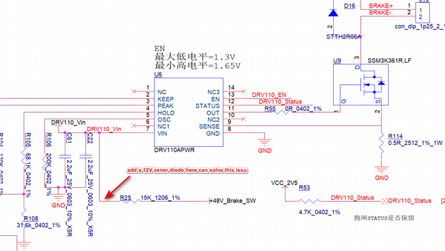
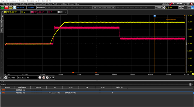
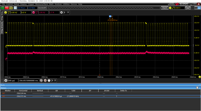
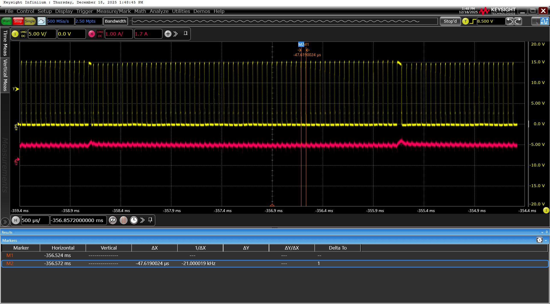
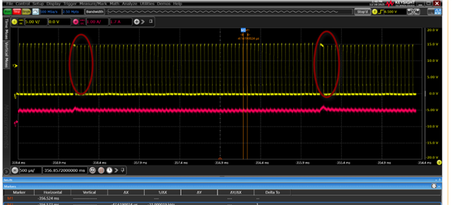
when I use DRV110 drive the Electromagnetic brake, I found if my pwer supply is 48V, then the VIN is going to be 15V, because of the function of 15V zener diode inside, but the OUT pin PWM frequency became unstable, and the Electromagnetic brake make a audible noise.
when I add a 12V zener diode at the VIN pin, let the 15V zener diode does not work, the
issue is solved.
Does the 15V zener work cause this issue?